Put rated DC across a transformer winding and the core is full in 3.75 milliseconds. Not 3.75 seconds. Milliseconds. At 60 Hz the sine wave never gives the flux more than 8.3 ms to climb before it drags it back down, and that reversal is the entire trick. DC has no reversal, so the countdown starts the moment you close the switch.
The answer in sixty seconds
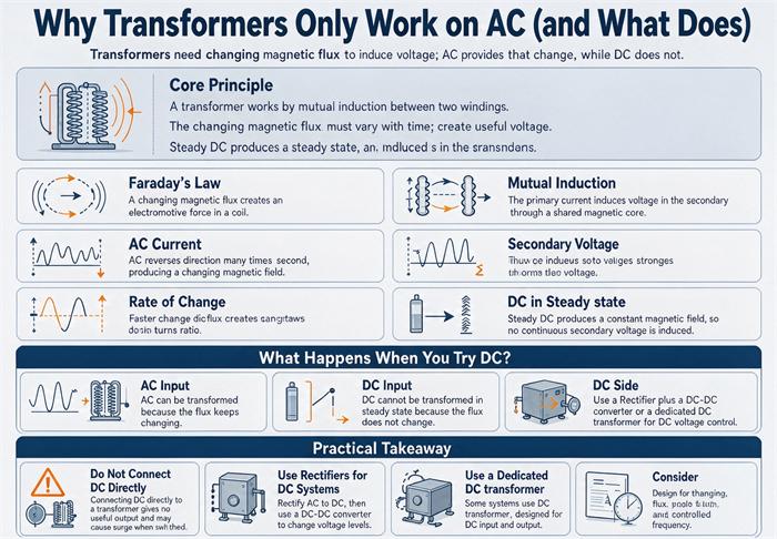
A transformer is two coils sharing a magnetic circuit. It does not connect the two circuits electrically. It couples them magnetically, and magnetic coupling only carries a changing flux. Faraday’s law is blunt about this: the voltage induced in the secondary is proportional to the rate of change of flux, V = N dΦ/dt. Hold the flux steady and the derivative is zero. No voltage appears on the secondary. Nothing transfers.
That is the textbook answer, and it is correct as far as it goes. It is also the least useful version for anyone standing in front of a real unit, because it explains why the output is zero without explaining why the input is about to become a fire.
The part the textbook skips is what happens on the primary side. A transformer winding is an inductor with a lot of turns on a high-permeability core, which means its magnetizing inductance is large. Large inductance is exactly what stops current from rising quickly. In AC, the voltage reverses every half cycle, so the current never gets far. In DC, the voltage never reverses. The current keeps climbing. The core keeps filling. And a core only holds so much.
Half a cycle is all the time AC needs to stay out of trouble. DC never gives you that half cycle back.
The real limit is volt-seconds, not volts
Why the core has a ceiling at all
The core is grain-oriented silicon steel, laminated to break up eddy currents. Its permeability is roughly a thousand times that of air, which is why it can guide flux from one winding to the other instead of letting it spray into the room. That permeability is not constant. It holds up to a point and then collapses.
That point is saturation flux density, usually written B_sat. For conventional grain-oriented electrical steel it runs about 1.9 to 2.0 tesla. For amorphous metal cores it is about 1.56 tesla, which surprises people who assume the newer material is better at everything. Amorphous metal has far lower core loss, and that is why it gets used in distribution transformers. It also saturates earlier, so the same flux needs more core area or more turns. If a supplier tells you an amorphous unit has more saturation headroom, they have it backwards.
Designers normally run the core at 1.5 to 1.7 tesla at rated voltage, which leaves 15 to 25 percent of margin before the knee. That margin exists for overvoltage, for frequency sag, and for the small DC that loads sometimes inject. It is not much, and it is not free.
3.75 milliseconds, at any voltage, at any size
Here is the arithmetic that makes this concrete, and it produces a number almost nobody quotes.
For a sine wave of RMS voltage V at frequency f, the peak flux linkage is:
Φ_max = V / (√2 · π · f)Apply a DC voltage V_dc and the flux ramps linearly. It reaches Φ_max in:
t_sat = Φ_max / V_dc = V / (√2 · π · f · V_dc)Read that last line carefully. The rated voltage V appears in the numerator, and the applied DC appears in the denominator. If the DC equals the rated RMS voltage, the two cancel. What is left is:
t_sat = 1 / (√2 · π · f)Frequency is the only variable. Not kVA. Not voltage class. Not the size of the core.
| System frequency | Time to saturate on rated DC | One half cycle |
|---|---|---|
| 50 Hz | 4.5 ms | 10 ms |
| 60 Hz | 3.75 ms | 8.33 ms |
| 400 Hz (aircraft, some UPS) | 0.56 ms | 1.25 ms |
Now the worst case, because it does not start from zero flux. If the core happened to be at negative peak when you closed the switch, the flux has to travel the full swing, 2·Φ_max, which doubles the time. At 60 Hz that is 7.5 ms against a half cycle of 8.33 ms.
So even in the most forgiving starting condition, DC runs out of core before a single half cycle of normal AC would have completed. That is the whole reason AC works. The sine wave is a machine for reversing the flux just before it runs out of room, sixty times a second, forever.
The same arithmetic explains 50 Hz on a 60 Hz nameplate
The formula above has one more consequence that buyers run into constantly, and it is worth pulling out because it costs people real money on export projects.
Flux is proportional to voltage divided by frequency. That ratio, usually written V/Hz, is the actual rating of a transformer core. Not volts. Volts per hertz.
| Nameplate | Design V/Hz at rated voltage | Applied at 60 Hz, 480 V | Applied at 50 Hz, 480 V |
|---|---|---|---|
| 480 V, 60 Hz | 8.0 | 8.0 (100% of design flux) | 9.6 (120%, saturated) |
| 480 V, 50 Hz | 9.6 | 8.0 (83%, comfortable margin) | 9.6 (100%) |
A 60 Hz unit run at 50 Hz on the same voltage has 20 percent more flux than it was built for. If it was designed at 1.6 T, it is now asking the core for 1.92 T, which is past the knee. The unit hums louder, draws more exciting current, runs hot, and the protection may or may not notice before the insulation does.
The reverse direction is generous. A 50 Hz design on a 60 Hz supply runs at 83 percent of its design flux, which means cooler core, quieter operation, and margin to spare. This is why a 50 Hz unit is the safe choice for a project that might ship to either market, and why a 60 Hz unit sold into a 50 Hz country is a claim waiting to happen.
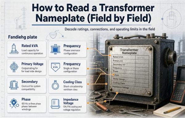
Nameplate reading matters here more than anywhere else, and the field procedure for the voltage, frequency, and impedance fields is set out in how to read a transformer nameplate and technical parameters. Check the hertz before you check anything else.
What that number means in practice
A 1 kVA control transformer and a 100 MVA generator step-up unit saturate on the same clock, provided the DC equals their rated winding voltage. The physics does not care about the nameplate.
What changes with size is not whether it saturates but how much energy is available to wreck it. A 1 kVA unit might pull 80 amps before something upstream gives. A 2,000 kVA unit pulls enough to open a main breaker and take a section of the plant with it.
What actually happens when DC hits the winding
Millisecond 1: the secondary does twitch
There is a moment where the transformer appears to work. While the flux is still climbing, dΦ/dt is not zero, so a voltage does appear on the secondary. It starts near the turns ratio and decays as the flux approaches the ceiling.
This is where the “it worked for a second” stories come from, and it is why a quick bench test with a multimeter can be misleading. You see a reading. You conclude the transformer is fine. Three seconds later the reading is zero and the winding is hot.
A voltmeter is slow. Human reaction is slower. By the time you have decided the reading looks reasonable, the transient is long gone.
Millisecond 4: the core fills up
At saturation, the incremental permeability drops from thousands to roughly that of air. The winding stops being an inductor and becomes a coil of copper wire with a resistance of a few ohms, or a few milliohms on a large unit.
Two things follow immediately. The secondary voltage collapses to near zero, because there is no longer a changing flux to link. And the primary current is now limited only by resistance and by whatever impedance sits upstream. A transformer at that moment is not a transformer. It is a short circuit that happens to be shaped like a transformer.
Second 30: I²R with nothing in the way
Run the numbers on something small, because small is where people do this by accident.
A 1 kVA, 120 V single-phase unit. Rated current is 8.33 A. Magnetizing current at rated voltage is about 3 percent of that, so roughly 0.25 A. Primary DC resistance is around 1.5 ohms.
Apply 120 V DC and Ohm’s law gives 80 amps.
That is 9.6 times the rated current, and 320 times the magnetizing current the winding was designed to carry continuously. The heat is I²R, which is 9.6 kW. The same unit is designed to shed about 20 W of total loss at full load, so the dissipation is roughly 480 times design.
Now the thermal side. Take 6 kg of copper at 385 J per kg per kelvin. Reaching a 150 K rise takes 346 kJ, which at 9.6 kW arrives in about 36 seconds. At 200 K it is 48 seconds. The enamel on modern magnet wire is rated 155 to 200 °C, and the paper is charring around the same point, both far below the 1,085 °C where copper actually melts. The winding does not need to melt to fail. It only needs to lose its insulation.
So the honest answer to “what happens if I connect this to DC” is: it runs for a few seconds, produces smoke, and then produces an open circuit.
Scale it up and the same arithmetic gets worse, because resistance falls faster than current-carrying capacity rises. On a 1000 kVA, 480 V three-phase unit the rated current is 1,203 A and the equivalent series resistance is around 3 milliohms. Divide 480 by 0.003 and the theoretical current is 150,000 A. No source delivers that, so what actually limits the current is the upstream breaker, not the transformer. Either way the transformer is a busbar with a winding wrapped around it.
| Stage | Time from closing the switch | What is happening | What you would measure |
|---|---|---|---|
| Flux ramp | 0 to 3.75 ms (60 Hz) | Core still linear, flux climbing at a constant rate | Secondary voltage present, decaying |
| Saturation | 3.75 to 7.5 ms | Permeability collapses, inductance falls by orders of magnitude | Secondary near zero, primary current spiking |
| Current limit | 10 ms to 1 s | Only winding resistance and source impedance remain | Primary current tens to hundreds of times rated |
| Thermal | 20 s to 2 min | I²R in a winding sized for 2 percent loss | Smoke, smell, insulation failure |
| Open circuit | Minutes | Conductor fuses or insulation carbonizes | Zero current, dead unit |
If the DC is small, it does not kill it. It ages it.
Full rated DC on a winding is an accident. A few amps of DC on a big unit is a condition, and it is far more common than most people realize.
The mechanism is the same but the outcome is different. A small DC shifts the operating point on the B-H curve. The core is no longer centered. One half cycle reaches saturation before the other does, so the exciting current becomes lopsided. Excess flux spills out of the core into the tank wall, the clamping structure, and the frame, where it induces eddy currents and local hot spots that no oil temperature gauge will ever see. This is the same stray-flux mechanism that makes cooling class matter, and the temperature rise that shows up on the tank rather than in the oil is covered in transformer cooling classes explained.
The symptoms stack up in a recognizable order: noise first, then harmonic distortion in the exciting current, then stray-flux heating on the tank, then gassing, then a failed unit that everyone describes as having died for no reason.
There is a clean diagnostic signature here, and it is worth memorizing.
| Condition | Harmonic pattern in exciting current | Timing |
|---|---|---|
| Overvoltage, symmetric saturation | Odd harmonics, mostly 3rd and 5th | Present whenever voltage is high |
| DC bias, asymmetric saturation | Even harmonics, mostly 2nd and 4th | Persistent in steady state |
| Inrush at energization | Large 2nd harmonic | Seconds, then decays |
That second row is the one people miss. Differential relays use the 2nd harmonic to tell inrush from a real fault, and they block on it. So a sustained 2nd harmonic reading in normal operation is not inrush. Inrush is over. Something is pushing DC into the core, and the relay that was designed to ignore 2nd harmonic is now ignoring the actual problem.
The case you will actually meet: partial DC
Half-wave rectifiers and the lopsided current
A half-wave rectifier takes current from the secondary in one direction only. That DC component has to come from somewhere, and it comes through the transformer. Reflected to the primary, it becomes a DC magnetizing current superimposed on the AC.
Where this shows up in real plants: legacy single-diode circuits nobody documented, cheap single-phase battery chargers of the kind built on single-phase cylindrical winding transformers, half-controlled thyristor heating controls running at low firing angle, cheap battery chargers, and a failed diode inside an otherwise healthy three-phase bridge. That last one is the nasty version, because the rectifier still works, the process still runs, and the only clue is a transformer running hotter and louder than it should.
The fix is usually boring. Replace the half-wave circuit with full-wave. Replace the failed bridge. If the circuit is inherent to the process, derate the transformer and state the DC component in the specification so the designer can add core area.
DC injection from HVDC ground return and solar inverters
High-voltage DC transmission uses the earth as a return conductor in monopolar mode, and during faults in bipolar mode. That earth current does not stay in the ground. It finds grounded neutrals on nearby wye-connected transformers and goes through them, at magnitudes from a couple of amps to tens of amps depending on distance and soil resistivity.
Geomagnetic storms do the same thing on a continental scale. The 1989 storm took down the Hydro-Québec system in 92 seconds and left 6 million customers dark for nine hours. GIC in some transmission lines exceeded 100 amps, and two transformers at the Chibougamau substation were permanently damaged. The NOAA Space Weather Prediction Center publishes storm forecasts, and utilities in high-latitude regions plan around them.
Solar is the opposite case, and it is reassuring. A grid-tied inverter must limit DC injection to 0.5 percent of rated output current under IEEE 1547 and UL 1741. On a 1000 kW array at 480 V that is 6 amps of DC. The limit exists because the industry decided even small DC matters to the transformer. It does, over twenty years. Projects that size a transformer behind an inverter array usually start from renewable energy transformer selection for exactly this reason.
The same logic covers the DC fast charging case, which confuses people who read the label instead of the single line. A 350 kW charger takes AC in, transforms it, rectifies it, and sends DC out to the vehicle. The transformer is on the AC side of that chain, which is why a DC charging site still needs a conventional packaged substation for DC fast charging. The word DC describes the cable, not the transformer.
Residual magnetism after a DC test
This one costs money on almost every project and almost nobody plans for it.
Winding resistance tests push DC through the winding. So does a DC hipot. Both leave the core magnetized, sometimes at a substantial fraction of saturation. Energize that unit without demagnetizing it and the inrush can double, because the residual flux adds to the first half cycle instead of subtracting from it.
The result is a differential relay trip on energization, a crew that spends a day looking for a fault that does not exist, and a supplier who gets blamed for a commissioning procedure. The fix takes twenty minutes: demagnetize with a reduced AC voltage and wind it down slowly, or use a dedicated demagnetizing set. Put it on the commissioning checklist next to the torque values.
Stray current from DC traction
Subway and light rail systems return traction current through the running rails, and not all of it stays there. A fraction leaks into the earth and finds grounded neutrals. The magnitude is small per unit, but it is continuous during service hours, and the affected transformers sit there slowly saturating on one half cycle.
If your site is within a few hundred meters of a DC traction line, this belongs in the design conversation rather than the post-mortem. Our rail transit traction transformer work deals with this directly, because traction duty brings its own harmonic and DC profile on top of the stray current question.
How to find it in the field
You suspect DC. Here is the half hour that settles it, in order of cost.
Step 1: read the neutral
On a grounded wye unit, clamp a meter around the neutral conductor and switch it to DC. A healthy system reads close to zero. A few amps means something is pushing DC through the earth and your neutral is one of the paths. This is the single fastest test and it costs nothing.
Do it during the hours when the suspected source is running, because DC traction and industrial rectifiers follow a schedule.
Step 2: compare the two half cycles
Put a current clamp on the primary and look at the waveform, not the RMS number. Under pure AC the positive and negative peaks are near enough to mirror images. Under DC bias they are not. One peak is higher and the current has a flat-topped or sharply spiked shape on that side.
An RMS meter averages this away. That is why so many DC problems get signed off as “current is within nameplate.” The RMS value can be perfectly normal while the waveform is badly asymmetric.
Step 3: look for the 2nd harmonic
If you have relay records or a power quality analyzer, check the harmonic spectrum of the current. A 2nd harmonic above roughly 5 percent of fundamental, present steadily rather than for a few seconds after energization, points at DC. Symmetric saturation from overvoltage gives you 3rd and 5th instead.
Step 4: compare the phases
On a three-phase unit, unequal phase currents that are not explained by unbalanced load point at a failed diode in a rectifier bridge or a partial winding problem. A bridge with one open diode behaves like a half-wave rectifier for part of the cycle, which is exactly the DC injection case above.
Step 5: check for residual flux before blaming the design
If the unit trips a differential relay every time it energizes and then runs fine, the problem is probably residual magnetism from a DC test or a previous interrupted energization, not a design fault. Demagnetize it and try again before you open a warranty claim.
| What you measure | Healthy reading | DC present |
|---|---|---|
| Neutral DC current | Under 0.5 A on a clean system | 2 A to 50 A depending on source |
| Positive vs negative peak | Within a few percent | 10 to 40 percent apart |
| 2nd harmonic, steady state | Under 2% of fundamental | 5% and up |
| Phase current balance | Matches the load imbalance | Unexplained 10% spread |
| Noise, sudden change | Stable over months | Rose after a load was added |
Why AC won, in money
The transmission arithmetic
The reason AC became the standard is not elegance. It is that a transformer is the only cheap, static, efficient way to change voltage, and changing voltage is the only way to move power a long distance without throwing most of it away.
Line loss is I²R. Raise the voltage by a factor of ten and the current falls by ten, so the loss falls by a hundred. Nothing else in the system has that pull.
Take 100 MW moving 100 km over a line with 5 ohms of total resistance:
| Sending voltage | Line current | Loss over 100 km | Share of 100 MW |
|---|---|---|---|
| 13.8 kV | 4,184 A | 87.5 MW | 87.5% |
| 34.5 kV | 1,674 A | 14.0 MW | 14.0% |
| 69 kV | 837 A | 3.50 MW | 3.50% |
| 138 kV | 418 A | 875 kW | 0.88% |
| 345 kV | 167 A | 140 kW | 0.14% |
| 765 kV | 75.5 A | 28.5 kW | 0.03% |
At distribution voltage you cannot deliver the power at all. Most of it lands in the conductor. At 345 kV you lose a seventh of one percent. The difference between those two rows is a transformer, and there is no DC equivalent that is remotely as cheap or as reliable.
This is why the transformer and the AC grid are the same invention. AC needs the transformer to be useful. The transformer needs AC to function at all. Either one alone is a curiosity.
The part DC has since won back
DC has come back for very long distances, for submarine cables, and for tying together grids that are not synchronized. That is real and growing.
It did not remove transformers. It added a new type. Every HVDC terminal has converter transformers on its AC side, sized for the harmonic spectrum the valve produces, with special insulation coordination and unusually high test levels. A ±800 kV link has more transformer steel in it than the AC line it replaced, not less.
The exceptions people get wrong
DC-DC converters do have transformers
Open a 48 V to 12 V converter and you will find a transformer in it. That does not contradict anything above. The converter chops the DC into high-frequency AC, typically 100 kHz to 1 MHz, pushes that through the transformer, and rectifies the output. The transformer only ever sees alternating voltage.
This is why those transformers are tiny. The volt-second product per cycle falls with frequency, so at 200 kHz the core can be a fiftieth the size of a 60 Hz core handling the same power. If you want a “DC transformer,” the answer is a switching converter, and the transformer inside it is still an AC device.
HVDC does not skip transformers
Covered above, but it comes up often enough to repeat. The DC side of an HVDC link has smoothing reactors, filter banks, and valve halls. It does not have transformers, because a transformer cannot pass DC. The transformers are all on the AC side, at both ends.
Pulse and flyback: DC that works, for microseconds
A flyback converter applies DC to a winding, stores energy in the core, then switches off and lets the flux collapse. This works because the on-time is short and there is a reset interval that returns the flux to its starting point before the next pulse.
The governing rule is volt-second balance: over one complete cycle, the integral of voltage with respect to time must be zero.
∫ v(t) dt = 0 over one full cycleBreak that rule and the flux walks upward a little each cycle until the core saturates. In a gate drive transformer with 20 turns on a 2 × 10⁻⁵ m² ferrite core, 12 V of DC saturates it in about 11 microseconds, because ferrite saturates around 0.35 T rather than 2 T. The principle is identical to the 3.75 ms figure. The only difference is that the core is small, so the volt-second budget is small.
So a transformer can handle DC in the sense that it can handle a pulse of it. What it cannot do is handle DC continuously, because continuous DC means the volt-second integral never comes back to zero.
Current transformers and DC offset
A CT is a transformer, so it inherits the same limit. During a fault, the fault current has a DC offset that decays with the system time constant, typically 10 to 50 ms on a distribution system and longer on a transmission system. That offset drives the CT core toward saturation, and a saturated CT produces a distorted secondary current.
Protection engineers handle this by specifying the CT knee point and the accuracy limit factor, and by accounting for the DC time constant. It is the same physics as a power transformer on DC, just applied to a measurement winding that is not supposed to carry power at all.
If your load is not clean AC: what to put in the RFQ
Most transformer specifications describe the source and forget the load. The load is where DC comes from.
| Load type | What it puts into the transformer | What to specify |
|---|---|---|
| Six-pulse rectifier | Harmonics 5, 7, 11, 13. No DC if healthy | Harmonic spectrum or K-factor, plus the actual THD |
| Half-controlled thyristor | DC at low firing angles | DC bias tolerance, asymmetric current test at factory |
| Half-wave / single diode | Substantial DC | Do not use a standard unit. Full-wave the circuit or derate hard |
| Arc furnace, welding | Intermittent DC plus flicker | K-factor, duty cycle, and a DC component limit |
| Grid-tied inverter | DC injection capped at 0.5% of rated current | Standard unit, but confirm THD and IEEE 1547 compliance |
| DC traction nearby | Stray DC into the neutral | DC blocking provision in the neutral, or a lower flux density design |
| HVDC electrode nearby | Tens of amps through the neutral | Neutral blocking device, lower flux density, monitoring |
The RFQ line that prevents most of these arguments:
Load description:
  Load type ...................... [six-pulse VFD / half-controlled / arc / inverter]
  Total harmonic current distortion ... [___] % at full load
  DC component in load current .... [___] A or "none expected"
  If DC is possible, state the source and duty cycle

Transformer requirements:
  Excitation current at rated voltage . [___] A, asymmetry limit [___] %
  Factory test: asymmetric excitation current at 110% rated voltage
  DC bias tolerance ................ [___] A without exceeding rated temperature rise
  Core flux density at rated voltage . [___] T (state it; do not leave it to the supplier)
  Neutral arrangement .............. [grounded wye / delta / resistance grounded]
Two notes on that list.
The flux density line is the one that matters most and gets specified least. A unit designed at 1.6 T has more DC headroom than one designed at 1.75 T, and the price difference is core steel. If you are near DC traction, near an HVDC electrode, or running a half-controlled load, that line is worth more than any warranty clause.
The amorphous line is the one that catches people. Amorphous metal has lower core loss and lower saturation flux density. On a site with DC bias risk, it gives you less margin, not more. If a supplier offers amorphous as the answer to a DC problem, ask for the flux density and the excitation current at 110 percent voltage before you sign.
If you are comparing a 50 Hz design against a 60 Hz design for an export project, the flux arithmetic changes too, and that comparison is worked through in IEC 60076 vs ANSI/IEEE standards for export transformers. A 50 Hz core on a 60 Hz system has margin to spare. The reverse is how units arrive saturated.
FAQ
Why can a transformer not pass DC?
A transformer transfers energy through a changing magnetic flux. The secondary voltage equals the number of turns times the rate of change of flux. DC produces a flux that is constant once the current settles, so the rate of change is zero and no voltage appears on the secondary. The primary side is worse: with no reversal, the current keeps rising until the core saturates, and then only winding resistance limits it.
How fast does a transformer saturate on DC?
At 60 Hz, rated DC saturates the core in 3.75 milliseconds. At 50 Hz it takes 4.5 ms, and at 400 Hz about 0.56 ms. The time depends only on frequency, not on kVA or voltage class, because rated voltage and core flux scale together. In the worst case, starting from negative peak flux, it takes twice as long, which is still less than one half cycle of normal AC.
What happens if I connect 120 V DC to a 120 V AC transformer?
The winding draws about 80 amps through roughly 1.5 ohms, against a rated current of 8.33 A. That is 9.6 kW of heat in a unit designed to shed about 20 W. The copper reaches a 150 K rise in roughly 36 seconds, the enamel and paper fail, and the winding opens. You get a few seconds of secondary voltage during the initial flux ramp, then nothing but smoke.
Can a transformer work on pulsed DC?
Yes, and this is how every DC-DC converter works. A pulse is a changing flux, so the secondary does respond. What matters is volt-second balance: over one complete cycle the integral of voltage must return to zero, or the flux walks upward until the core saturates. Flyback and forward converters therefore need a reset interval, a reset winding, or a symmetric drive to bring the flux back each cycle.
Does DC bias destroy a transformer immediately?
No. A few amps of DC shifts the operating point, saturates one half cycle earlier than the other, and produces stray flux that heats the tank wall. The damage is thermal and chemical rather than sudden: hotter windings, faster insulation aging, gassing, and noise. Units can run for years this way. They just do not reach their design life, and the failure looks unexplained when it comes.
How do I tell DC bias from plain overload?
Look at the harmonics in the exciting current. Symmetric saturation from overvoltage produces odd harmonics, mostly 3rd and 5th. DC bias produces even harmonics, mostly 2nd and 4th, and they persist in steady state. Inrush also produces a large 2nd harmonic, but it decays within seconds. A 2nd harmonic that is still there an hour after energization is not inrush.
Do solar inverters inject DC into the transformer?
They are allowed to, up to 0.5 percent of rated output current under IEEE 1547 and UL 1741. On a 1000 kW array at 480 V that is about 6 amps. It is small enough that a standard distribution transformer handles it without derating. The limit exists because the industry decided the effect on insulation aging over twenty years was worth capping. Storage inverters follow the same rule.
Why do DC fast chargers still use AC transformers?
Because the transformer sits on the AC side of the charger, not the DC side. Grid power arrives as AC, goes through the transformer for voltage conversion and isolation, then into a rectifier that produces the DC the vehicle needs. The cable and the vehicle see DC. The transformer never does. That is why a 350 kW charger still needs a conventional medium-voltage transformer behind it.
Does an amorphous core handle DC better?
No, it handles it worse. Amorphous metal has much lower core loss, which is why it is popular for distribution transformers, but its saturation flux density is about 1.56 T against roughly 2.0 T for grain-oriented silicon steel. Lower saturation means less headroom before the knee. On a site with DC bias risk, an amorphous unit needs more core area to match the DC tolerance of a conventional design.
What is volt-second balance?
It is the rule that a transformer core must receive equal positive and negative volt-seconds over each operating cycle. Volt-seconds are voltage multiplied by time, and they are what actually fills the core. A 480 V pulse for 1 ms and a 48 V pulse for 10 ms carry the same volt-seconds. If the positive and negative areas do not cancel, residual flux accumulates cycle after cycle until the core saturates, which is the mechanism behind every “DC transformer” failure.
Free: Transformer Specification Checklist
The exact RFQ sheet our engineers use — send it and get a quoted proposal within 24h.
Download checklist