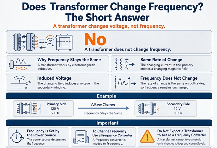
No. A transformer moves voltage, current, and phase, and it moves all three at exactly the frequency it was handed. 60 Hz in, 60 Hz out, to the last decimal, on a 5 kVA control transformer and a 500 MVA generator step-up alike. Frequency is a property of the flux, and there is only one flux.
That answer takes ten seconds. The useful part is everything that follows from it, because most people who ask the question are not asking about physics. They are standing in front of a machine built for 50 Hz, in a plant fed at 60 Hz, and someone has told them a transformer will sort it out. It will not, and the money that gets spent finding that out is real.
The direct answer, in a table
| You put in | You get out | Why |
|---|---|---|
| 480 V, 60 Hz | 208 V, 60 Hz | Turns ratio 2.308, frequency untouched |
| 480 V, 60 Hz | 480 V, 60 Hz | An isolation unit, ratio 1.000 |
| 400 V, 50 Hz | 230 V, 50 Hz | Ratio 1.739, frequency untouched |
| 115 V, 400 Hz | 115 V, 400 Hz | Ratio 1.000, frequency untouched |
| 480 V, 60 Hz | Nothing useful | That is a rectifier and an inverter, not a transformer |
Read that last row twice. It is the entire commercial problem in one line.
One flux, one frequency
The reason the frequency cannot change is simpler than most explanations make it, and it is worth getting exactly right because every downstream consequence follows from it.
Two windings sit on one core. The primary current makes a magnetic flux in that core. That flux is not per winding. There is one flux, shared, threading both coils. Faraday’s law says the voltage induced in a winding is the number of turns times the rate of change of that shared flux:
e = N × dΦ/dtLook at what is in that expression. The turns number N is different for the two windings. That is the whole point of a transformer, and it is why 2,400 primary turns against 1,040 secondary turns gives you 480 V in and 208 V out.
The dΦ/dt is not different. It is the same flux, changing at the same rate, seen by both coils at the same instant. So the time signature is identical on both sides. The period is identical. The frequency is identical. The turns ratio scales the amplitude of the wave and touches nothing else about its shape or its timing.
Here is the least mathematical way to say it. A transformer is a lever for voltage. A lever multiplies force. It does not change how fast you push the handle. If you push once a second, the load moves once a second, no matter how long the lever is.
That is also why this answer does not depend on size, voltage class, or application. A doorbell transformer and a 500 MVA generator step-up are the same argument, because they are the same physics. If a supplier ever tells you their transformer has a “50 Hz output” from a 60 Hz input, they are describing a product that does not exist, and the specification will not survive commissioning.
Everything in is everything out
One consequence people miss: a transformer does not filter frequency either. It cannot create a frequency and it cannot remove one. Whatever is in the input waveform comes out the secondary, at the same frequencies, in the same proportions except for the amplitude scaling.
Put 60 Hz plus 5 percent fifth harmonic into a transformer and you get 60 Hz plus 5 percent fifth harmonic out, at the new voltage. The transformer’s impedance is frequency dependent, so the harmonic sees a higher impedance than the fundamental and the voltage distortion at the secondary is usually a little worse than at the primary. But the frequencies themselves pass straight through.
This is why a transformer is not a harmonic solution. It is a harmonic bystander. If your drive load is putting 8 percent THD on the bus, buying an isolation transformer changes where the distortion lands. It does not reduce it, and in most cases the added impedance makes the voltage notch deeper at the load end.
What a transformer actually changes
Four things, and the fourth one is the one that causes arguments.
Voltage and current, in inverse proportion
The obvious pair. A 1000 kVA unit at 480 V carries 1,203 A on the primary and 2,776 A on the secondary at 208 V. Power in equals power out minus losses, so when voltage goes down by 2.308, current goes up by 2.308.
Phase angle, which is the thing people mistake for frequency
This is where the confusion starts, and it deserves its own section rather than a sentence.
A three-phase transformer shifts the phase of the secondary voltage relative to the primary. That shift is set by how the windings are connected, and it is written into the vector group on the nameplate. The clock notation is literal: each hour on the clock face is 30 electrical degrees.
| Vector group | Primary | Secondary | Secondary lags primary by |
|---|---|---|---|
| Dyn1 | Delta | Star, neutral | 30° |
| Dyn11 | Delta | Star, neutral | 330° (or 30° leading) |
| Yyn0 | Star, neutral | Star, neutral | 0° |
| Yd11 | Star, neutral | Delta | 330° |
| Dd0 | Delta | Delta | 0° |
A Dyn11 unit shifts the secondary 30° away from the primary. Thirty degrees every cycle. At 60 Hz, one cycle is 16.67 ms, so the shift is 1.39 ms of time. And then the next cycle does exactly the same thing, and the next one after that, forever.
So the frequency has not moved. What moved is where in the cycle the wave sits. Frequency is how often the wave repeats. Phase is where it starts. Two quantities, one confusion.
This matters commercially because of what happens when two units with different vector groups are paralleled. The circulating current is set by the phase difference and the sum of the impedances:
| Phase difference | Vector sum of the two secondaries | Circulating current, %Z 6% each |
|---|---|---|
| 0° (matched) | 0 | 0 |
| 30° (Dyn11 against Dyn1) | 0.518 pu | 4.31 × rated |
| 60° (Dyn11 against Dyn5) | 1.000 pu | 8.33 × rated |
| 120° | 1.732 pu | 14.43 × rated |
| 180° | 2.000 pu | 16.67 × rated |
A 4.31 times rated circulating current appears before you close a single load breaker. The protection may not trip, because the current is balanced and looks like load. The units cook. And the person diagnosing it will usually say the two transformers are “on different frequencies” or “out of phase on frequency,” which is the wrong name for a real problem.
If you are adding a second unit in parallel, the vector group, the turns ratio, and the impedance all have to match. The frequency matches itself, because there is nothing you can do to make it not match.
Impedance, and this is where frequency re-enters
Here is the part almost nobody writes down. Percent impedance is not a constant. It is quoted at a stated frequency, and its dominant component scales with frequency.
The reactive part of the impedance is:
X = 2 × π × f × LInductance L is fixed by the geometry. Frequency f is not. So a transformer’s reactance is linear in frequency, and its percent impedance moves when the supply frequency moves.
That single relationship produces the two most expensive surprises in this whole subject: the derating you have to apply when a 60 Hz unit runs at 50 Hz, and the fault current that quietly goes up when you move a machine to a 50 Hz site.
When the frequency is wrong
Three cases. Each has a different answer, and only one of them is dangerous.
A 60 Hz unit on a 50 Hz supply: 83.3 percent of the voltage
The flux in the core is proportional to voltage divided by frequency. That ratio, V/Hz, is the real rating of a transformer core, and it is a fixed design number.
| Nameplate | Design V/Hz | At rated voltage and frequency | Same unit at the other frequency |
|---|---|---|---|
| 480 V, 60 Hz | 8.00 | 8.00 | At 50 Hz: 480/50 = 9.60, which is 120% of design |
| 400 V, 50 Hz | 8.00 | 8.00 | At 60 Hz: 400/60 = 6.67, which is 83% of design |
| 460 V, 60 Hz | 7.67 | 7.67 | At 50 Hz: 460/50 = 9.20, which is 120% of design |
| 380 V, 50 Hz | 7.60 | 7.60 | At 60 Hz: 380/60 = 6.33, which is 83% of design |
A 480 V, 60 Hz unit held at 480 V on a 50 Hz supply is asking its core for 20 percent more flux than it was designed for. If it was built at 1.6 T, it is now at 1.92 T, which is past the knee of the curve. Exciting current climbs steeply, the unit gets louder, stray flux heats the tank and the structural steel, and the winding temperature rises for reasons the oil gauge will show but not explain.
The correct way to run it is to hold the ratio, which means dropping the voltage:
- 480 V unit becomes a 400 V unit at 50 Hz
- 4,160 V unit becomes 3,467 V at 50 Hz
- 1,000 kVA becomes 833 kVA, because current stays at 1,203 A and voltage dropped by 5/6
That last line is the one to put in a quote. A 1000 kVA transformer on a 50 Hz supply is an 833 kVA transformer. Not because anything is damaged, but because the current limit and the flux limit no longer coincide at the same voltage.
There is a small consolation that most write-ups miss. Core loss goes down, not up, when you hold the flux constant and drop the frequency, because hysteresis loss is roughly proportional to frequency and eddy current loss to frequency squared:
| Loss component | Scaling | At 50 Hz versus 60 Hz |
|---|---|---|
| Hysteresis | ∝ f | × 0.833 |
| Eddy current | ∝ f² | × 0.694 |
| Total core loss, 60 percent hysteresis and 40 percent eddy | × 0.78, about 22 percent lower |
So the derated unit runs cooler than it did at nameplate. You lose 17 percent of the capacity and gain thermal margin. That said, a modern unit built to the 2029 DOE loss limits starts from a lower core loss than a 1990s unit, so the absolute numbers on an old transformer will be worse than the ratio suggests. That is a fair trade if the load is 800 kVA. It is not a fair trade if the load is 1,000 kVA and someone assumed the nameplate was the answer.
A 50 Hz unit on a 60 Hz supply: the free direction
Reverse it and the arithmetic is generous. A 50 Hz design at 60 Hz runs at 83 percent of its design flux at rated voltage. Cooler core, quieter operation, lower core loss, and margin in hand.
This is why a 50 Hz design is the safe order for any project that might ship to either market, and why the export conversation usually ends with “specify it as a 50 Hz unit and it will work anywhere.” The one caveat is that you have to check the accessories, not the transformer. Fans, pumps, and control transformers on the unit have their own frequency ratings, and a 60 Hz cooling fan on a 50 Hz supply runs at 5/6 speed and moves noticeably less air. The main unit is fine. The thing keeping it cool is not.
400 Hz through a 60 Hz core
This is where the internet gets it wrong most often, usually with a confident sentence saying a 60 Hz transformer cannot be used at 400 Hz.
It can. It just cannot be used well at anywhere near its nameplate rating, and the reason is not saturation.
At 400 Hz with the voltage unchanged, the flux is only 15 percent of design, so the core is nowhere near its ceiling. If you raised the voltage to 6.67 times rated to restore the design flux, you would run into eddy current loss scaling with the square of frequency:
| Quantity | At 400 Hz versus 60 Hz |
|---|---|
| Flux, same voltage and same turns | × 0.15 |
| Hysteresis loss | × 6.67 |
| Eddy current loss | × 44.4 |
| Leakage reactance | × 6.67 |
| Core cross section needed for the same volts per turn | × 0.15 |
Forty-four times the eddy loss is why you cannot simply spin a 60 Hz core faster at design flux. The laminations are too thick. Eddy current loss goes with the square of lamination thickness as well as the square of frequency, so 400 Hz designs use much thinner steel, and above a few kHz they stop using steel altogether and use ferrite.
And the leakage reactance rising by 6.67 times is the practical killer at any voltage. Leakage reactance is what causes voltage regulation, so a 60 Hz unit at 400 Hz with a 5 percent regulation becomes a unit with roughly 33 percent regulation. The output collapses under load. It will pass a signal. It will not run a load.
So the accurate statement is: a 60 Hz transformer will pass 400 Hz at a small fraction of its kVA, with poor regulation, and it is the wrong part for the job. Aviation uses 400 Hz because the core cross section needed for a given volts per turn is 15 percent of the 60 Hz figure, and that weight saving is worth the thinner laminations and the litz wire. The frequency is chosen for the hardware. The hardware does not create the frequency.
The fault current nobody adjusts
Here is the consequence with the least coverage anywhere and the most direct safety implication.
Percent impedance is quoted at rated frequency. Move a unit to a lower frequency and the reactive part of its impedance falls in proportion, while the resistive part stays put.
| X/R at rated frequency | Z at 60 Hz | Z at 50 Hz | Impedance drop | Fault current increase |
|---|---|---|---|---|
| 2 | 2.236 | 1.944 | 13.1% | +15.0% |
| 4 | 4.123 | 3.480 | 15.6% | +18.5% |
| 6 | 6.083 | 5.099 | 16.2% | +19.3% |
| 8 | 8.062 | 6.741 | 16.4% | +19.6% |
| 10 | 10.050 | 8.393 | 16.5% | +19.7% |
Distribution transformers run X/R between about 2 and 8, so the realistic range is 15 to 19 percent more available fault current on a 50 Hz supply than the 60 Hz study predicted.
Put numbers on it. A 1000 kVA unit at 5.75 percent impedance gives 20.9 kA of bolted fault at 480 V on a 60 Hz system. Drop the impedance by 16 percent for 50 Hz operation and the same unit delivers 24.9 kA. If the switchboard was selected at 22 kA because the 60 Hz study said 20.9, you are now 13 percent past the rating of the gear, and nothing about the installation looks different. The interrupting rating requirement in NEC Article 110.9 is written against the available fault current, not against the current somebody calculated in another country.
Nobody re-runs the short circuit study when a plant moves country. The transformer arrives, the gear arrives, the commissioning test passes, and the interrupting rating is quietly wrong. This is a paperwork failure, not an equipment failure, which is exactly why it survives commissioning.
The consequences that travel downstream
The transformer does not change the frequency. It does faithfully deliver whatever it was given, and the equipment downstream is where the frequency shows up as a problem.
Motor speed follows frequency, not voltage
Induction motor speed is set by the supply frequency and the pole count:
n = 120 × f / p| Poles | At 60 Hz | At 50 Hz | At 400 Hz |
|---|---|---|---|
| 2 | 3,600 rpm | 3,000 rpm | 24,000 rpm |
| 4 | 1,800 rpm | 1,500 rpm | 12,000 rpm |
| 6 | 1,200 rpm | 1,000 rpm | 8,000 rpm |
| 8 | 900 rpm | 750 rpm | 6,000 rpm |
| 12 | 600 rpm | 500 rpm | 4,000 rpm |
A 4-pole motor is 1,800 rpm on 60 Hz and 1,500 rpm on 50 Hz. That is 16.7 percent slower, and no transformer on earth changes it. If a conveyor is running slow after a plant relocation, the transformer is not the suspect. The frequency is.
What that does to a pump or a fan
For centrifugal loads the affinity laws turn a speed change into a much larger power change:
| Quantity | Scaling with speed | At 5/6 speed (50 Hz on a 60 Hz motor) |
|---|---|---|
| Flow | ∝ n | 0.833 |
| Head or pressure | ∝ n² | 0.694 |
| Shaft power | ∝ n³ | 0.579 |
A pump that moved 1,000 gpm at 60 Hz moves 833 gpm at 50 Hz and draws 58 percent of the power. That sounds like a bargain until you check the process requirement, which was written for 1,000 gpm. The pump is now undersized by 17 percent on flow and the motor is oversized by 42 percent on power, which is the worst of both arrangements.
Run the other direction and it gets dangerous. A 50 Hz pump on a 60 Hz supply runs at 1.2 times speed, moves 20 percent more flow, and draws 1.2 cubed, which is 73 percent more power. The motor nameplate did not change. The overload relay setting probably did not change either, because nobody thought about it.
The machine that runs, badly
The classic import case: a European machine built for 400 V, 50 Hz, installed in a US plant with 480 V, 60 Hz available. The voltage half of that gap is exactly what a UL listed 480 V to 380 V transformer is for, and it is worth being clear that the transformer fixes the 100 V and does nothing at all about the 10 Hz.
Left alone, the machine runs 20 percent fast. V/Hz drops from 8.0 to 8.0 if the voltage matches the ratio, or to 6.67 if the machine keeps its 400 V rating on a 480 V supply, which means a weaker field, less torque per amp, and a motor that draws more current to do the same work. Every timer in the control circuit runs 17 percent fast. Every fan runs 20 percent fast and 73 percent harder. Every 50 Hz rated contactor coil sees 60 Hz and either chatters or holds with less margin.
A transformer can fix exactly one of those problems, the voltage. It cannot touch the other five. This is why an export project that starts with “we’ll just add a transformer” usually ends with a frequency converter and a transformer, in that order, at about twice the budget.
The transformer on the output of a drive
One case where frequency genuinely does vary at a transformer terminal, and it is not the transformer’s doing.
A drive takes 60 Hz in, rectifies it to DC, and synthesizes a variable frequency output. Put a transformer on that output and the transformer now sees a pulse width modulated waveform at anywhere from a few hundred hertz to a couple of kilohertz of switching, with a fundamental that moves. Three things follow:
- Harmonic heating. The winding loss rises with the square of frequency for the eddy component. A standard unit derates.
- Insulation stress. The dv/dt of an IGBT output is measured in kilovolts per microsecond, and it arrives at the first turns of the winding harder than any 60 Hz sine ever would.
- Common mode voltage. The drive’s output is not balanced about ground, and a transformer between the drive and the motor changes the ground path.
Put the transformer on the input side and none of this applies. It sees 60 Hz, it does its normal job, and the drive does the frequency. That placement decision is worth more than any specification argument about the transformer itself.
What actually changes frequency
Six technologies, and only one of them has the word transformer on it.
| Technology | How it works | Frequency range | Typical use |
|---|---|---|---|
| Static frequency converter | AC, DC link, inverter | Any fixed output, 50/60/400 Hz | Export test benches, avionics ground power |
| Motor-generator set | An electric motor driving a generator at a different speed or pole count | Fixed by the speed and pole ratio | Legacy plants, high power, harsh loads |
| Variable frequency drive | AC, DC link, inverter with variable modulation | Continuously variable, typically 0 to 400 Hz | Motor speed control |
| Cycloconverter | Direct AC to AC, no DC link | Output below about one third of input | Very large mill and kiln drives |
| HVDC back to back | Rectifier, DC link, inverter | Any, each end independent | Asynchronous ties between 50 Hz and 60 Hz grids |
| Solid-state transformer | AC, DC, medium frequency transformer, DC, AC | Any, at either terminal | Emerging, data centers, traction |
The motor-generator set, in numbers
Old technology, still the right answer above a few megawatts and in any plant where the load is ugly.
The trick is that output frequency is set by shaft speed and generator pole count, not by input frequency. A 4-pole induction motor on 60 Hz turns at 1,800 rpm minus slip. Couple it to a 4-pole generator and you get 60 Hz back out, which is an isolation set rather than a converter. Couple it to a generator wound for a different pole count, or drive it through a reduction gear, and the output changes.
The real products show the engineering:
| Design | Motor | Generator | Output | Accuracy |
|---|---|---|---|---|
| Belt drive, 5 to 313 kVA | 4-pole, 1,800 rpm | 4-pole, 1,500 rpm | 50 Hz | ± 1.5%, from belt slip |
| Reduction gear, 375 to 1,250 kVA | 4-pole, 1,800 rpm | 4-pole, 1,500 rpm | 50 Hz | ± 0.5%, from motor slip |
| Direct, 25 to 2,000 kVA | 12-pole synchronous | 10-pole synchronous, 600 rpm | 50 Hz | Exact, 10 × 600 / 120 |
That last row is the elegant one. The common shaft turns at 600 rpm. A 12-pole motor at 600 rpm needs 60 Hz, and a 10-pole generator at 600 rpm produces 50 Hz. No gear, no belt, no slip, and the ratio is exactly 5/6 because the pole ratio is exactly 6/5. It is also the quietest of the three, which is why it shows up in military and utility installations rather than in a rented test bay.
Notice what is doing the work: a motor and a generator. Two rotating machines, each of which has its own frequency relationship to speed. The transformer, if there is one in the lineup, is there to fix the voltage on one side or the other. It is not there to fix the frequency.
The solid-state transformer, the one real exception
If a transformer is going to change frequency, this is the only architecture where that sentence is true, and it is worth being precise about why.
A solid-state transformer has a converter on the input, a converter on the output, and a transformer between them running at a medium frequency measured in kilohertz rather than hertz. The isolation is still magnetic. The transformer still has a core and windings and a turns ratio. But because both of its terminals are connected to power electronics rather than to the grid, the frequency at the input terminal and the frequency at the output terminal are set by the converters, not by the transformer.
So it can take 50 Hz in and deliver 60 Hz out, or 60 Hz in and deliver DC out, or 50 Hz in and deliver 400 Hz out. The medium frequency inside is what makes it small: at 20 kHz instead of 60 Hz, the core cross section for a given volts per turn is smaller by a factor of 333, which is why these units are the size of a refrigerator rather than a shipping container.
Two honest caveats. The device is a converter with a transformer inside, and calling it a transformer is a naming convention rather than a description. And the reason to buy one is not frequency conversion, which a plain converter does more cheaply. It is voltage transformation with galvanic isolation and power quality control in one package, usually at medium voltage. If your actual requirement is 60 Hz to 50 Hz for a 40 kVA machine, a solid-state transformer is a very expensive way to solve it.
The mistake that costs the most
It has a predictable shape, and it starts with a specification line.
A buyer has a 50 Hz machine and a 60 Hz site. Somewhere in the RFQ, a line appears asking for a transformer with a “50 Hz output.” It gets quoted, because every transformer supplier will quote a transformer. What arrives is a unit that passes 60 Hz from primary to secondary, exactly as physics requires, and the machine is still wrong.
The cost is not just the transformer. It is the transformer, the switchgear, the installation, the commissioning trip, the delay on the production line, and then the frequency converter that was needed in the first place, now installed downstream of a transformer that is doing nothing useful except adding impedance and losses. On a 200 kVA load, that is a five figure mistake made of nothing but a badly worded sentence.
The decision table is short enough to memorize:
| Your situation | What fixes it | What does not |
|---|---|---|
| 50 Hz machine, 60 Hz site, motor loads only | Frequency converter sized for the motor starting | A transformer |
| 50 Hz machine, 60 Hz site, mostly electronics and heaters | Often nothing, check each load individually | A transformer, and usually a converter too |
| 60 Hz transformer on a 50 Hz site, load below 83% | Reconnect for 400 V and run it | Running it at 480 V |
| 60 Hz transformer on a 50 Hz site, load above 83% | A 50 Hz design, or two units | Derating and hoping |
| Voltage mismatch only, frequency the same | A transformer | Anything else |
| Parallel units, different vector groups | Match the vector group | Blaming the frequency |
Read the second row carefully, because it is the one that saves the most money. If the machine is a packaging line with servo drives, PLCs, and resistance heaters, most of it does not care about frequency at all. Switch mode power supplies accept 50 or 60 Hz. Heaters do not care. Servo drives rectify the input before they use it. The only frequency sensitive parts are the line frequency induction motors and any 50 Hz contactor coils, and those are often cheaper to replace than the converter is to buy.
That audit, load by load, is worth doing before anything gets ordered. It is also the fastest way to turn a five figure problem into a four figure one.
What to put in the RFQ
Six lines. Each one prevents a specific failure.
1. Supply frequency at the site: ______ Hz
2. Required output frequency: same as supply (state this explicitly)
3. V/Hz basis: ______ V per Hz at rated point
4. Dual rated 50/60 Hz: yes / no
5. Vector group: ______ (must match any unit in parallel)
6. Short circuit study basis: ______ kA at ______ Hz
Line 2 looks silly and it is the most valuable line on the page. Writing “same as supply” in the specification is how you find out in the quotation stage, rather than at commissioning, whether the person across the table understands what a transformer does.
Line 3 is how you catch a unit that will be asked to run at the wrong flux. If you state 8.00 V/Hz and the supplier quotes a 60 Hz design for a 50 Hz site at 480 V, the numbers will not reconcile and the conversation happens before the purchase order.
Line 6 is the one nobody includes and the one that protects the switchgear. If the unit is going to a 50 Hz site, the fault current will be roughly 15 to 19 percent higher than a 60 Hz study predicts, and the gear has to be selected on the 50 Hz number.
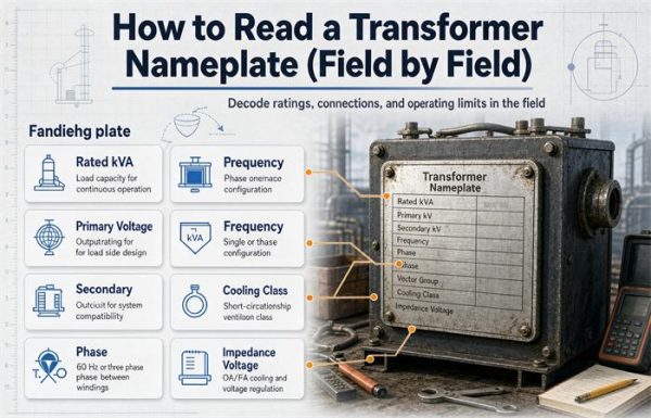
If you are working across the 50/60 Hz boundary on an export project, the standard and testing differences go wider than frequency, and they are set out in IEC 60076 versus ANSI/IEEE standards for export transformers. The frequency field on the plate is one line of many, and the procedure for reading the rest of it, including the vector group and the impedance base, is in how to read a transformer nameplate.
Where frequency decides the product
Two product categories exist because of frequency, and both are worth knowing about if you are specifying rather than troubleshooting.
At 400 Hz the core shrinks to 15 percent of the 60 Hz cross section for the same volts per turn, which is why aircraft electrical systems run there and why ground power units are converters rather than transformers. On the grid side the same logic runs the other way: a generator step-up unit is built around one system frequency, and the selection criteria for those units are set out in step-up transformers in renewable energy. At line frequency, the opposite applies. An induction furnace fed at 50 or 60 Hz needs a core and a winding sized for that frequency, and the whole design of a power frequency furnace transformer follows from it, including the high secondary current and the tap range.
The same logic applies in marine and traction work, where dual frequency capability is a procurement requirement rather than a feature. Shipboard systems are 60 Hz on most of the world’s fleet and 50 Hz on others, and a marine transformer has to be ordered for the right one or ordered dual rated. Rail is the same story with a wrinkle: traction supplies differ by country in both voltage and frequency, which is why rail transit traction transformers are usually specified against a list of supply conditions rather than a single one.
The short version
- A transformer cannot change frequency, because both windings share one flux and the rate of change of that flux is common to both. Turns scale amplitude only.
- What it changes is voltage, current, phase angle, and impedance. The phase shift is real and is often mistaken for a frequency problem.
- Percent impedance is quoted at a rated frequency, and its reactive part scales with frequency. Moving a 60 Hz unit to a 50 Hz site raises the available fault current by 15 to 19 percent.
- A 60 Hz unit on 50 Hz runs at 83.3 percent of its voltage and 83.3 percent of its kVA, with lower core loss. A 50 Hz unit on 60 Hz is the safe direction.
- Anything that genuinely converts frequency is an active device: a static converter, a motor-generator set, a drive, a cycloconverter, an HVDC tie, or a solid-state transformer. None of them is a plain transformer, and the last one only qualifies because it has converters on both ends.
FAQ
Does a transformer change frequency?
No. A transformer passes whatever frequency it is given, unchanged, because both windings link the same magnetic flux and the rate of change of that flux is identical for both. A 60 Hz input produces a 60 Hz output at the new voltage, and a 50 Hz input produces a 50 Hz output. Changing frequency requires an active device with power electronics or rotating machines, not a passive magnetic component.
Can a transformer convert 60 Hz to 50 Hz?
No. This is the most common version of the question and the answer does not change with size or price. A transformer has no mechanism to alter the period of the waveform, because the waveform is defined by the flux it shares rather than by either winding alone. Converting 60 Hz to 50 Hz needs a static frequency converter, a motor-generator set, or a drive, and those are separate equipment from the transformer.
What happens if I run a 60 Hz transformer at 50 Hz?
At the same voltage it saturates, because flux is proportional to voltage divided by frequency and the ratio rises by 20 percent. Run it at 400 V instead of 480 V and it is fine, but it is now an 833 kVA unit rather than a 1000 kVA unit, since current stays at 1,203 A while voltage drops. Core loss also falls by about 22 percent, so the derated unit runs cooler than it did at nameplate.
Does a 50 Hz transformer work on 60 Hz?
Yes, and it is the safer direction. At rated voltage a 50 Hz design on a 60 Hz supply runs at 83 percent of its design flux, which means a cooler core, lower core loss, quieter operation, and thermal margin. The unit can carry its rated kVA at its rated voltage. Check the accessories separately, because a 60 Hz cooling fan on a 50 Hz supply runs slower and moves less air even though the transformer itself is happy.
Why do aircraft use 400 Hz instead of 60 Hz?
Because the core cross section needed for a given volts per turn is inversely proportional to frequency. At 400 Hz that is 15 percent of the 60 Hz figure, so transformers and motors on the aircraft are far smaller and lighter, which saves fuel and payload over the life of the airframe. The trade is much higher eddy current loss, which is handled with thin laminations, and much higher leakage reactance, which is handled with short cable runs.
Does a transformer change phase?
Yes, and this is the quantity people mistake for frequency. A three-phase transformer shifts the secondary voltage relative to the primary by an amount set by its vector group, in steps of 30 electrical degrees per clock hour. Dyn11 lags by 30 degrees, Yyn0 shifts by zero. The shift repeats identically every cycle, so the frequency is unchanged. Paralleling units with mismatched vector groups causes large circulating current before any load is connected.
What does a transformer change besides voltage?
Three things: current, in inverse proportion to voltage; phase angle, set by the vector group; and impedance, which is quoted at a rated frequency and shifts when the frequency changes. Power is unchanged except for losses, and frequency in equals frequency out. That is the complete list, and it is short enough to be worth memorizing before any specification meeting.
Can a VFD be used as a frequency converter?
Sometimes, with limits. A drive produces a variable frequency output, so it can be set to a fixed 50 Hz, but its output is a modulated waveform rather than a clean sine, and it is designed for a motor load rather than for a panel of mixed equipment. Electronics, transformers, and anything with a rectifier front end generally do not tolerate it. A purpose built static frequency converter produces a filtered sine wave and is the correct part for supplying equipment rather than a motor.
Why did the available fault current change when we moved to a 50 Hz site?
Because percent impedance is quoted at rated frequency and its reactive part scales with frequency. Move a unit from 60 Hz to 50 Hz and the reactance falls by 5/6 while resistance stays, so the total impedance drops by 13 to 17 percent depending on the X/R ratio. The available fault current rises by 15 to 19 percent, and switchgear selected on a 60 Hz study may no longer have adequate interrupting rating.
Is a solid-state transformer really a transformer?
It contains one, but it is not only one. A solid-state transformer puts a converter on each terminal with a medium frequency transformer between them, running at kilohertz rather than at line frequency. The isolation is magnetic and the turns ratio still applies, but the input and output frequencies are set by the converters, which is why this is the only architecture where the sentence “the transformer changed the frequency” is accurate.
Free: Transformer Specification Checklist
The exact RFQ sheet our engineers use — send it and get a quoted proposal within 24h.
Download checklist