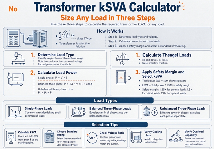
Size a transformer in three steps: add every load in kVA, multiply by 1.25 if any of it runs three hours or more, then round up to the next standard rating and check the ambient, altitude and harmonics. A web calculator does the middle step for you. This page shows all three, with the arithmetic spelled out and the traps marked.
Five calculators on the first page of Google will give you five different answers for the same load, and none of them is broken. The difference is the margin each one assumes before it rounds up. One page tells you to add 120 percent and then prints a formula that divides by 0.8, which is 125 percent. Another defaults to 20 percent growth. A third multiplies kW by 1.25, which converts power factor and calls it margin. Those are three different products, and the price gap between them is real.
So the useful thing to learn is not the formula. kVA = volts × amps ÷ 1,000 takes four seconds to memorize and the calculator already knows it. The useful thing is the three decisions wrapped around the formula: what counts as load, which margin you are buying, and which standard size is actually available on the shelf. Get those wrong and the arithmetic is perfect and the answer is still wrong.
The three steps at a glance
| Step | What you do | The arithmetic | What comes out |
|---|---|---|---|
| 1 | Build the load list | Nameplate amps, or kW plus power factor, for every load the transformer will feed | Connected load in amps or kW |
| 2 | Convert to kVA | Single phase: V × A ÷ 1,000. Three phase: 1.732 × V × A ÷ 1,000. From kW: kW ÷ PF | Minimum kVA at 100 percent loading |
| 3 | Margin, round, derate | Multiply by 1.25 for continuous load, round up to a standard rating, then correct for altitude, ambient and harmonics | The size you actually order |
Everything below is one of those three rows, expanded. If you already have a number and only want to check it, jump to the worked examples in step 2 and the rounding traps in step 3.
Step 1: Build a load list you can defend
A calculator input field is a promise that you already know the number. Most sizing mistakes are made here, before any arithmetic happens, because the person typing has a machine nameplate in one hand and a project schedule in the other.
Read the nameplate, not the sales sheet
The nameplate gives you rated voltage, rated frequency, rated current, phase, and usually a kVA or kW figure. The sales sheet gives you the same numbers rounded for a brochure and sometimes for a different voltage variant of the same machine. If you are looking at a piece of equipment you have never seen, the nameplate is the only document that describes the object in front of you. We wrote a full field by field walkthrough of how to read a transformer nameplate if you want the parameter list, but for sizing you need exactly four fields: volts, amps, phases, hertz.
Two refinements matter. First, motor nameplate amps are not the number the electrical code uses. NEC 430.6(A)(1) sends you to Table 430.250 for general purpose motors, and the table value usually runs a little above the nameplate, deliberately, because the table is built on worst case efficiency at each horsepower. Second, an inverter driven motor nameplate lists input amps and output amps, and they are not the same. The input side is what the transformer sees, including the drive’s own losses and its displacement power factor, which is close to 0.95 to 0.98 on a modern drive with a choke. Use the input rating.
Three ways a load arrives at your desk
Loads come in three shapes, and each one needs a different first move.
| What you have | What it tells you | First move |
|---|---|---|
| Amps and volts | Current the load draws at rated output | Multiply by voltage, then by 1.732 for three phase |
| kW and power factor | Real power plus how much reactive power rides along | Divide kW by PF to get kVA |
| kVA directly | Apparent power, already what you need | Add it up and go to step 3 |
| HP only | Shaft output, not electrical input | Convert to kW at 0.746, then divide by efficiency, then by PF, or just use Table 430.250 |
That last row is where a surprising amount of money gets lost. A 50 HP motor is 37.3 kW of shaft power. At 90 percent efficiency it draws 41.4 kW at the terminals. At 0.85 power factor that is 48.8 kVA. Table 430.250 gives the same motor 65 amps at 460 volts, which is 54.0 kVA at 480 volts. The code table sits about 10 percent above the efficiency and power factor estimate on purpose, and the table value is the one to size on.
Single phase loads on a three phase service
This is the most common place where a hand calculation and a calculator part company. A panel with 120 volt branch circuits spread across three phases is not sized by adding the three phase currents and multiplying by 120.
Take a panel fed at 208Y/120 volts with neutral connected loads of 28 amps on L1, 31 amps on L2 and 26 amps on L3. The total connected load is 120 × 28 + 120 × 31 + 120 × 26 = 10,200 VA, or 10.2 kVA. But a transformer does not average its phases. The hottest winding sets the limit, so the honest figure is three times the largest phase: 3 × 120 × 31 = 11,160 VA, or 11.2 kVA. That is 9 percent more than the simple sum, and the gap grows with imbalance.
The practical rule for a mixed panel is to balance first and size second. Move 3 amps of load from L2 to L3 and the largest phase drops to 28, which cuts the equivalent load to 10.1 kVA. Rebalancing is free. A larger transformer is not.
Motors, and the 125 percent that applies to only one of them
NEC 430.24 sizes a feeder supplying several motors as 125 percent of the largest motor’s full load current plus 100 percent of the rest. Not 125 percent of everything. That distinction matters when a calculator offers a single “safety margin” slider, because applying 125 percent to the total is more conservative than the code requires and can push you past a standard size you did not need to skip.
On a list of a 50 HP, a 20 HP and a 10 HP motor at 480 volts, Table 430.250 gives 65, 27 and 14 amps. The code feeder is 1.25 × 65 + 27 + 14 = 122.3 amps, or 101.6 kVA. Multiply the whole 106 amp total by 1.25 and you get 132.5 amps, or 110.2 kVA. Both land on a 112.5 kVA unit, so the shortcut costs nothing here. On a longer list with one dominant motor it can cost you a size, and on a list with three equal motors it is the correct answer by accident.
Demand factor: not everything runs at once
Article 220 exists because a building with 400 kVA of connected load does not draw 400 kVA. Lighting demand factors, receptacle demand factors and the motor diversity that any real facility has all reduce the number. A calculator that adds every nameplate at 100 percent will oversize a mixed commercial panel by 30 to 50 percent, and an oversized transformer is not free: you pay for the copper, you carry higher no load loss for twenty five years, and you get a higher available fault current at the secondary.
The honest middle path is to apply demand factors where the code or the facility’s own history supports them, and to document the assumption next to the number. “We assumed 70 percent diversity on the receptacle load based on the 2025 interval data” is a defensible sentence in a submittal. “We used 100 percent because the calculator had one field” is not.
Step 2: Convert everything to kVA
Two formulas cover almost every load you will meet. Write them once and the rest is bookkeeping.
Single phase:   kVA = (volts × amps) ÷ 1,000
Three phase:    kVA = (1.732 × volts × amps) ÷ 1,000
From real power: kVA = kW ÷ power factor
From kVA:        amps = (kVA × 1,000) ÷ (1.732 × volts)   [three phase]
The 1.732 is the square root of three, and it appears because three phase power is the sum of three sinusoidal quantities displaced by 120 degrees. You do not need to derive it. You do need to remember that it multiplies line to line voltage, not line to neutral.
The 277 versus 480 mistake
On a 480Y/277 volt system there are two voltages on the nameplate of every load, and picking the wrong one is the single most common calculator error we see in RFQs. A 100 amp load at 480 volts three phase is 83.1 kVA. The same 100 amps taken at 277 volts, which is the line to neutral value, computes to 27.7 kVA on a single phase formula, or 48.0 kVA if someone multiplies by 1.732 anyway. The three answers span a factor of three, and only one of them is right.
The rule is mechanical: for a three phase load, use the line to line voltage and the current in one conductor. For a single phase load connected line to neutral, use the line to neutral voltage. Never mix the two in one formula. If a load is connected line to line on a three phase system, at 480 volts for example, it is a single phase load at 480 volts and the single phase formula applies.
Three phase kVA in one line
A 480 volt, three phase, 120 amp machine draws 1.732 × 480 × 120 ÷ 1,000 = 99.8 kVA. That is the minimum size at 100 percent loading. Multiply by 1.25 and you get 124.7 kVA, and the next standard three phase rating above that is 150 kVA. The unit will run at 66.5 percent of nameplate, which is a comfortable place to be and leaves room for the next machine.
A 150 kVA unit at 480 volts carries 180.4 amps per phase at full load. Your 120 amp load is two thirds of that. If you want the reverse calculation, the same identity gives amps from kVA: 150,000 ÷ (1.732 × 480) = 180.4.
Power factor, and why 0.8 is a habit rather than a rule
Transformers are rated in kVA because the winding has to carry both the current that does work and the current that maintains magnetic fields. Power factor is the ratio between the two, and it is a property of the load, not of the transformer.
| Load type | Typical power factor | What it does to your kVA |
|---|---|---|
| Resistance heating, incandescent | 1.00 | kVA equals kW, no penalty |
| Modern LED drivers, electronic PSU | 0.90 to 0.98 | Small penalty, often corrected internally |
| Induction motors, fully loaded | 0.85 to 0.90 | Moderate penalty |
| Induction motors, lightly loaded | 0.60 to 0.75 | Large penalty, and it gets worse below half load |
| Welding transformers, induction furnaces | 0.50 to 0.80 | Severe penalty, often needs correction |
| Data center with active PFC supplies | 0.95 to 0.99 | Almost no penalty |
| Uncorrected rectifier or DC charger | 0.60 to 0.85 | Severe penalty plus harmonics |
The 0.8 default that most calculators use is a 1960s industrial average. It is a safe assumption for a mixed motor load and a bad assumption for a data hall, where 0.95 is closer to the truth, and for a lightly loaded motor, where 0.65 might be optimistic. A 100 kW load at 0.95 needs 105 kVA. The same 100 kW at 0.65 needs 154 kVA. That is a 46 percent swing on one assumption, and it is the reason the power factor field matters more than the voltage field on any calculator.
The multiply by 1.25 that is not margin
One widely copied shortcut says size a three phase transformer at kW × 1.25. That number is correct arithmetic and wrong accounting. Dividing kW by 0.8 power factor gives kVA, and 1 ÷ 0.8 is 1.25. So kW × 1.25 is the kVA at 0.8 power factor with zero margin, zero growth allowance, and zero continuous load factor.
Run a 20 kW motor through it and you get 25 kVA, which is a 100 percent loaded transformer the day it is energized. Apply the continuous load factor as well and the requirement is 31.25 kVA, which rounds to 45 kVA on the three phase ladder because 30 kVA is below the requirement and 37.5 kVA is a single phase size. The shortcut understates the order by 80 percent. If you want a single rule of thumb that survives both steps, it is kW × 1.5625 at 0.8 power factor, and that still assumes the motor runs at full load.
Three worked examples
All three start from a real input shape you will see in an RFQ, and all three end at a standard rating.
Example A. Amps known. A 480 volt, three phase, 120 amp machine. kVA = 1.732 × 480 × 120 ÷ 1,000 = 99.8 kVA. With the 1.25 continuous factor, 124.7 kVA. Next standard three phase rating: 150 kVA. Loading at the design load: 66.5 percent.
Example B. kW and power factor known. 90 kW at 0.85 power factor. kVA = 90 ÷ 0.85 = 105.9 kVA. With 1.25: 132.3 kVA. Next standard rating: 150 kVA. Loading: 70.6 percent. Note that 112.5 kVA looks tempting and is short by 19.8 kVA, which is the kind of gap that shows up as a hot transformer in July.
Example C. A mixed 208Y/120 panel. Neutral loads of 28, 31 and 26 amps plus a 208 volt three phase 40 amp load. Phase loads: 3 × 120 × 31 = 11,160 VA. Three phase load: 1.732 × 208 × 40 = 14,410 VA. Total 25,570 VA, or 25.6 kVA. With 1.25: 32.0 kVA. Next standard three phase rating: 45 kVA, because 30 kVA would leave the panel at 85 percent before any growth. Loading: 56.8 percent.
| Example | Input | kVA at 100% | × 1.25 | Standard size | Loading |
|---|---|---|---|---|---|
| A | 480 V, 3φ, 120 A | 99.8 | 124.7 | 150 kVA | 66.5% |
| B | 90 kW at PF 0.85 | 105.9 | 132.3 | 150 kVA | 70.6% |
| C | Mixed panel, 208Y/120 | 25.6 | 32.0 | 45 kVA | 56.8% |
Step 3: Margin, standard size, and derating
The conversion gives you a number that no factory builds. This step turns it into an order line.
Where the 125 percent actually comes from
Here is a correction that will save an argument with an inspector. Article 450 does not set a loading limit for transformers. It sets the rules for protecting the transformer you already bought, including the 125 percent primary overcurrent device in Table 450.3(B) for units with a primary full load current of 9 amps or more.
The 125 percent continuous factor lives in 215.2 and 215.3, and it applies to feeder conductors and overcurrent devices: not less than 125 percent of the continuous load plus 100 percent of the noncontinuous load. Sizing the transformer at 125 percent of a continuous load keeps the whole feeder inside those rules, which is why the number appears in every sizing guide.
So when a calculator prints “size at 80 percent per NEC,” the conclusion is sound and the citation is loose. Article 450 has no 80 percent rule. The 80 percent is the other side of the 125 percent in 215.2, applied to the transformer as a design convention. Load a transformer to 80 percent and you are following the intent. Just do not tell an inspector it is a 450 requirement.
The practical version: continuous loads, meaning three hours or more, get the 1.25. Noncontinuous loads do not. If a load is 60 percent continuous and 40 percent noncontinuous, the blended factor is 0.6 × 1.25 + 0.4 × 1.00 = 1.15, and using 1.25 on the whole thing is a 9 percent oversize that you will pay for in copper.
The standard kVA ladder
Transformers are built to preferred ratings, and the two ladders are not the same ladder. These are the ANSI/IEEE preferred values for distribution transformers at 601 volts and above, as listed in C57.12.00 for liquid immersed and C57.12.01 for dry type.
| Three phase (kVA) | Single phase (kVA) |
|---|---|
| 15 | 15 |
| 30 | 25 |
| 45 | 37.5 |
| 75 | 50 |
| 112.5 | 75 |
| 150 | 100 |
| 225 | 167 |
| 300 | 250 |
| 500 | 333 |
| 750 | 500 |
| 1000 | 667 |
| 1500 | 833 |
| 2000 | |
| 2500 |
Two patterns are worth memorizing because they prevent most rounding mistakes.
First, every three phase rating up to 300 kVA is exactly three times a single phase rating: 15 from 5, 30 from 10, 45 from 15, 75 from 25, 112.5 from 37.5, 150 from 50, 225 from 75, 300 from 100. That is not a coincidence, it is because a three phase bank was historically three single phase units. The pattern breaks above 300 kVA, where 167 × 3 = 501 and gets rounded to 500, 333 × 3 = 999 and becomes 1000, and 667 × 3 = 2001 and becomes 2000.
Second, the two ladders are offset, so a number that is standard on one is usually not on the other. 150 kVA is a three phase size and not a single phase size. Ask for a single phase unit near 150 kVA and the answer is 167. 100 kVA is a single phase size and not a three phase size; the three phase answer near it is 112.5. If your calculator rounds to 150 kVA and you are buying a single phase unit, you have just ordered a custom build.
The ÷3 test is the fast check. Divide your three phase answer by three and see whether the quotient is on the single phase ladder. 150 ÷ 3 = 50, yes. 112.5 ÷ 3 = 37.5, yes. 75 ÷ 3 = 25, yes. 500 ÷ 3 = 166.7, close to 167 but not exact, which tells you the pattern has already broken.
What these ratings cost in practice is a separate question, and it does not scale linearly with kVA. A 75 kVA and a 112.5 kVA unit often sit closer in price than the ratio suggests, because the frame, the enclosure and the labor to build it are much of the cost. If you are comparing delivered prices across the ladder, our pad mounted sizes and prices guide shows where the steps are steep and where they are flat.
Rounding traps that cost real money
Rounding up to the next standard size is the easy part. Three code details sit behind it.
Article 240.6(A) has no 900, no 1,400 and no 1,800. The standard overcurrent device ratings run 800, 1000, 1200, 1600, 2000, 2500, 3000, 4000, 5000, 6000. If your calculation lands on 900 amps, the next standard device is 1000, and a 450.3(B) calculation that assumed 900 is now 11 percent off.
Article 240.4(C) removes the next size up allowance above 800 amps. For conductors over 800 amps, the ampacity must be at least the device rating. Below 800 amps you may round up to the next standard device if the conductor ampacity does not match one. Above 800 amps there is no such permission, so a 1,600 amp device needs 1,600 amps of conductor, not 1,550.
A 450.3(B) calculation ends on a device, not a transformer. Table 450.3(B) allows primary only protection at 125 percent of primary full load current for units at 9 amps and above, with permission to go to the next standard rating. A 1,000 kVA unit at 480 volts has a primary full load current of 1,203 amps. 125 percent is 1,504 amps, and the next standard device is 1,600 amps. That 1,600 amp breaker is what drives the switchgear, not the transformer.
Four derating factors the calculator ignores
The nameplate kVA assumes reference conditions: 30 degrees C average ambient with a 40 degree maximum for liquid immersed units, 40 degrees C maximum ambient for dry type, and an altitude of 1,000 meters, which is 3,300 feet. Move away from those and the nameplate number is no longer the capacity you have.
| Factor | Reference condition | What happens away from it | What to ask for |
|---|---|---|---|
| Ambient temperature | 40 C maximum | Winding hot spot rises, insulation life falls, usable kVA falls | The manufacturer’s loading table at your design ambient |
| Altitude | 1,000 m (3,300 ft) | Air is thinner, cooling degrades, dielectric withstand drops | A written altitude correction, typically expressed as a percentage per 100 m |
| Harmonics | Linear load | Eddy and stray losses rise faster than the fundamental, hot spot runs away from the average | A K factor rating (K-4, K-13, K-20) or a C57.110 derating calculation |
| Enclosure and temperature rise | Ventilated indoor | A sealed or outdoor enclosure traps heat, a lower rise costs more and lasts longer | The rise in degrees C, and the kVA that goes with that rise |
On harmonics, one precision point that most sizing pages get backwards. A K-rated transformer is built to carry its nameplate kVA with a specified harmonic spectrum. A standard K-1 unit asked to feed the same load has to be derated to roughly 88 percent of nameplate for a K-13 spectrum, and to roughly 84 percent for K-20. Buying a K-13 unit does not clean up the harmonics. It buys you a transformer that will not cook while the harmonics pass through.
On temperature rise, a dry type unit quoted at 150 degrees C rise and one quoted at 80 degrees C rise can have the same frame and different kVA. The lower rise unit either carries more kVA in that frame or lives much longer at the same kVA. Compare kVA and rise together, never kVA alone. The cooling class printed on the nameplate, ONAN or ONAF or AN, tells you which cooling stages the unit is built for and therefore how much of that kVA depends on fans that can fail. Our cooling classes explainer walks through what each designation adds.
Three checks a kVA calculator cannot do
The arithmetic is done. These three checks decide whether the number survives contact with a real electrical system, and all three need information a two field calculator never asks for.
Motor starting and voltage dip
A NEMA Design B motor draws about six times its full load current at locked rotor. The 50 HP motor from earlier, at 65 amps running, pulls roughly 390 amps for the second or two it takes to accelerate. On a 75 kVA transformer at 480 volts with 4 percent impedance, the transformer’s own short circuit capacity is about 1,875 kVA. A 390 amp starting current at 480 volts is 324 kVA of demand, so the dip at the transformer terminals works out to roughly 17 percent by the simple impedance method, before you add feeder drop.
Seventeen percent is enough to drop contactors, reset drives and make the lights blink. Typical specifications cap the dip at 5 percent at the service and 10 percent at the motor terminals. The fixes are a bigger transformer, a soft starter, a drive, or a reduced voltage starter, and the choice is economic: one size up in transformer is often cheaper than a starter on a small motor and more expensive on a large one.
Note what this means for the sizing table. A transformer sized purely on running kVA is correct for thermal loading and wrong for starting. If the load is one large motor, size on starting and check thermal second. If the load is many small motors, size on thermal and check starting second.
Inrush current and the breaker that trips once
Energizing a transformer draws a current many times its rated value for a few cycles, because the core has to establish flux from a random point on the voltage wave. The first peak can reach about 12 times rated current. The breaker protecting the transformer is sized at 125 percent of rated current, and its instantaneous magnetic trip sits at roughly 10 times the breaker rating. Multiply those and the trip threshold is 12.5 times transformer rated current, against an inrush peak of 12 times. Four percent of margin.
That is the whole reason a transformer trips its main on the first energization and never again, and why the same unit trips at a different site with a different breaker. If you are chasing that problem, the sequence of fixes runs from raising the magnetic trip setting, to a breaker with a higher continuous rating, to a controlled energization scheme. The arithmetic above is the arithmetic you need either way, and it is worth running before you blame the transformer.
Fault current, and the 22 kA ceiling
Available fault current at the secondary is transformer full load current divided by percent impedance, ignoring the source. A 750 kVA unit at 480 volts carries 902 amps, and at the 5.75 percent impedance most units that size ship with, the bolted fault is 15.7 kA. That fits comfortably under a 22 kA rated panel.
Push to 1,500 kVA and the same impedance gives 1,804 ÷ 0.0575 = 31.4 kA. A 2,000 kVA unit gives 41.8 kA. So 22 kA switchgear and 22 kA panelboards are fine to about 750 kVA at 480 volts and impossible at 1,500 kVA without a higher impedance design, which brings its own voltage regulation penalty. Above that point you are buying 42 kA or 65 kA gear, and the gear often costs more than the transformer.
One trap in this area. Splitting a 1,500 kVA requirement into two 750 kVA units on the same bus does not reduce fault current. Each unit contributes 15.7 kA and the bus sees 31.4 kA, exactly what the single unit gave. The fault current follows total kVA and impedance, not the number of cans. Put the two units on separate buses with separate mains and each bus sees 15.7 kA, which is the version that actually solves the problem.
Above 1,000 kVA, the conductors decide
There is a capacity cliff at 480 volts that has nothing to do with transformers, and it catches people who size on kVA alone.
Three runs of 1,000 kcmil copper per phase, at the 75 degree C column, gives 545 amps each, or 1,635 amps total. At 480 volts that is 1,359 kVA. A 1,000 kVA unit needs 1,203 amps and fits in three runs of 600 kcmil at 420 amps each. A 1,500 kVA unit needs 1,804 amps and does not fit in any three run configuration, so you are into four runs per phase at minimum, and with the 125 percent continuous factor you need 2,255 amps, which is five runs of 750 kcmil per phase or a busway.
That changes the project. Five conduits per phase, five sets of lugs, a wider gear lineup and a much larger pull. On a 480 volt distribution upgrade, the decision between a 1,000 kVA and a 1,500 kVA unit is often made by the conduit schedule rather than by the load.
The same cliff appears on the medium voltage side in a different form. A 1,000 kVA unit at 13,800 volts draws 41.8 amps, which is a single small conductor. At 480 volts it draws 1,203 amps. Same transformer, two very different installations, and the primary voltage is what decides whether the project is easy.
kVA, kW, HP, amps: the four numbers people mix up
| You have | You want | Formula | Worked example |
|---|---|---|---|
| Amps and volts, three phase | kVA | 1.732 × V × A ÷ 1,000 | 480 V, 120 A = 99.8 kVA |
| kVA and volts, three phase | Amps | kVA × 1,000 ÷ (1.732 × V) | 150 kVA at 480 V = 180.4 A |
| kW and power factor | kVA | kW ÷ PF | 90 kW at 0.85 = 105.9 kVA |
| kVA and power factor | kW | kVA × PF | 150 kVA at 0.85 = 127.5 kW |
| HP | kW at the shaft | HP × 0.746 | 50 HP = 37.3 kW |
| HP, roughly | kVA at the terminals | HP × 0.746 ÷ (efficiency × PF) | 50 HP at 0.9 and 0.85 = 48.8 kVA |
| kVA | kW at full load | kVA × PF | 75 kVA at 0.9 = 67.5 kW |
The HP to kVA estimate is worth one more sentence, because the rule of thumb “1 HP is about 1 kVA” is close enough to be useful and far enough off to be dangerous. At 90 percent efficiency and 0.85 power factor, one horsepower needs 0.975 kVA, so the rule holds. At 80 percent efficiency and 0.75 power factor, which is a realistic small motor, one horsepower needs 1.24 kVA, and a 25 percent error on a 100 HP load is 25 kVA. Use the nameplate or Table 430.250 for anything above 10 HP.
Sizing for the load you will have in five years
A transformer is a twenty five to thirty year purchase and a five year decision. Three things are worth building in now.
A growth allowance you can name. Twenty percent is common on commercial work, thirty percent on industrial work with a phased build out. Write down which it is, because a 20 percent growth allowance on top of a 25 percent continuous factor is a 1.5 multiplier in total, and that is often the difference between 112.5 kVA and 150 kVA.
A spare breaker position, not a spare transformer. The cheapest growth capacity is a panel with room for one more feeder and a transformer running at 60 to 70 percent. That combination handles most additions without a new unit.
The 2029 efficiency table. DOE efficiency standards for distribution transformers were amended in 2024, with a compliance date of April 23, 2029 under 10 CFR 431.192 and the tables in 431.196. A unit ordered in 2026 with a delivery that slips past that date has to be built to the new table, and the new table is indexed by both kVA and BIL, so the same kVA at a different insulation level lands on a different efficiency requirement. That BIL column is also where an import spec usually goes wrong, and the IEC against ANSI/IEEE comparison covers which number a US inspector expects to see. If your project energizes in 2029 or later, ask the supplier for the efficiency at the 2029 values now, because a unit qualified only to the current table may not be shippable at the back end of the schedule.
What to send a supplier instead of a number
A single kVA number is the least useful thing you can put in an RFQ, because the supplier has to reverse engineer your assumptions to quote against it. Send these eight items instead and the quote comes back comparable to the next one.
- Primary voltage, secondary voltage, and whether the secondary is grounded wye, delta, or ungrounded
- Phase configuration on both sides, and the vector group if you have a preference
- Calculated load in kVA, with the power factor assumption written next to it
- Which loads are continuous, and the margin you applied
- Frequency, 60 Hz or 50 Hz, and whether the unit is dual rated
- Percent impedance you need, or the fault current you have to stay under
- Altitude, design ambient, indoor or outdoor, and the enclosure type
- The harmonics picture, meaning the K factor or the THD if drives are on the bus
Every one of those eight items changes the price or the lead time. Impedance alone can move a quote by 10 percent, because a higher impedance unit uses more copper to hold the same thermal performance. A K factor rating adds cost. An 80 degree C rise adds cost. An outdoor enclosure adds cost. A supplier who quotes a bare kVA number is quoting an average of all the units they have built, not the one you need.
FAQ
How do I calculate kVA for a three phase transformer?
Multiply line to line volts by amps, multiply by 1.732, and divide by 1,000. A 480 volt three phase load drawing 120 amps is 1.732 × 480 × 120 ÷ 1,000 = 99.8 kVA. Use line to line voltage, not line to neutral, and current in one conductor. Then apply your continuous load factor and round up to the next standard rating, which for 99.8 kVA at 125 percent is 150 kVA.
What size transformer do I need for 100 amps at 480 volts three phase?
100 amps at 480 volts three phase is 83.1 kVA. At 125 percent for continuous load that is 103.9 kVA, and the next standard three phase rating is 112.5 kVA. That unit carries 135.3 amps at full load, so your 100 amp load runs at 74 percent of nameplate. If the load is noncontinuous and you expect no growth, 112.5 kVA is still the right answer because 75 kVA would be over 100 percent loaded.
Should a transformer be loaded to 80 percent or 100 percent?
Both are legal and they buy different things. Article 450 sets protection rules, not a loading limit. The 80 percent figure is the 125 percent continuous load factor from Articles 215.2 and 215.3 applied to the transformer as a design convention. Loading to 80 percent keeps the feeder and overcurrent device inside those rules and leaves thermal margin. Loading to 100 percent on a continuous load runs the winding at its design hot spot for its whole life, which is shorter.
How much margin should I add when sizing a transformer?
Twenty five percent for a continuous load, meaning three hours or more, and zero to 20 percent for a noncontinuous load depending on duty cycle. Then add a separate growth allowance, 20 percent on commercial work and 30 percent on phased industrial work. Do not confuse the two. A 25 percent continuous factor plus 20 percent growth is a 1.5 multiplier in total, so a 100 kVA load becomes 150 kVA, not 125 kVA.
What is the next standard three phase size above 112.5 kVA?
150 kVA. The three phase ladder runs 15, 30, 45, 75, 112.5, 150, 225, 300, 500, 750, 1000, 1500, 2000 and 2500 kVA. Note that 37.5 kVA is a single phase size and not a three phase one, and that every three phase rating up to 300 kVA is exactly three times a single phase rating. Above 300 kVA that relationship breaks because of rounding.
How many amps does a 75 kVA transformer deliver at 480 volts?
90.2 amps per phase at full load, three phase. The identity is 75,000 ÷ (1.732 × 480) = 90.2. On the primary at 480 volts it is the same current for a 1:1 isolation unit, and 180.4 amps on a 240 volt secondary. Add 25 percent if you are checking a continuous load against that rating, which brings the usable figure to 72.2 amps.
Can I use a three phase transformer for a single phase load?
Yes, with a capacity limit. A three phase transformer feeding a single line to line load can only use about 58 percent of its nameplate kVA, because one winding pair carries all the current while the third phase sits idle. A 75 kVA three phase unit gives you roughly 43 kVA of single phase capacity that way. For a dedicated single phase load, buy a single phase unit; the ladder is different and the price per kVA is usually better.
Why does my calculator give a different answer than my supplier?
Because the margin policy is different, not the math. One page adds 120 percent, another divides by 0.8 which is 125 percent, a third defaults to 20 percent growth, and a fourth multiplies kW by 1.25 which converts power factor and adds no margin at all. On a 92 kVA load, 120 percent gives 110.4 kVA and a 112.5 kVA unit, while 125 percent gives 115 kVA and a 150 kVA unit. Ask which assumption is in the number before you compare prices.
Does a transformer kVA rating change with altitude or ambient temperature?
Yes. Nameplate kVA assumes a 40 degree C maximum ambient and an altitude of 1,000 meters, which is 3,300 feet. Above that altitude the air is thinner, cooling degrades and dielectric withstand drops, so the usable kVA falls. Above the design ambient the hot spot rises and insulation life falls. Ask the manufacturer for a written correction at your site conditions. Published factors vary by design, so a general rule of thumb is not a substitute for their table.
How do I size a transformer for a motor?
Start from Table 430.250 full load current, not the motor nameplate, because NEC 430.6(A)(1) sends you to the table for general purpose motors. A 50 HP, 460 volt motor is 65 amps, which is 54.0 kVA at 480 volts, and 67.5 kVA at 125 percent, so a 75 kVA unit. Then check starting: locked rotor current of about six times running current on a 75 kVA unit with 4 percent impedance produces roughly a 17 percent voltage dip.
What size transformer do I need for 200 amps at 240 volts single phase?
48 kVA at 100 percent loading, since 240 × 200 ÷ 1,000 = 48.0. At 125 percent that is 60 kVA, and the next standard single phase rating is 75 kVA, because 50 kVA is below the requirement. The 75 kVA unit carries 312.5 amps at 240 volts, so the 200 amp load runs at 64 percent. This is the case where the single phase ladder and the three phase ladder give different answers.
Is kVA the same as kW?
No, and the gap is power factor. kW is real power, the part that does work. kVA is apparent power, the total the winding has to carry including the reactive current that maintains magnetic fields. kVA = kW ÷ power factor, so a 90 kW load at 0.85 power factor needs 105.9 kVA. At 0.65 power factor the same 90 kW needs 138.5 kVA, which is a 31 percent larger transformer for identical useful output.
Free: Transformer Specification Checklist
The exact RFQ sheet our engineers use — send it and get a quoted proposal within 24h.
Download checklist