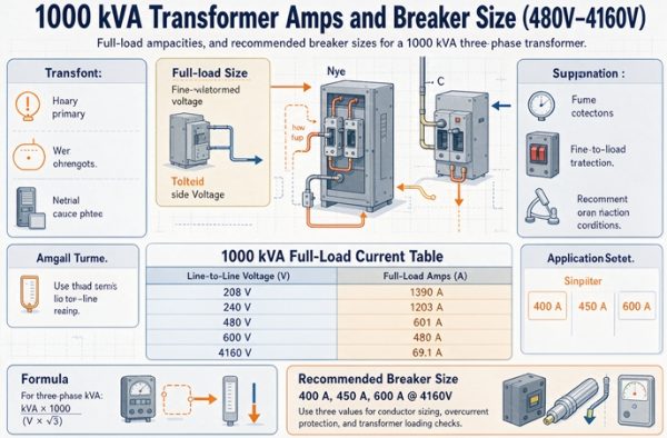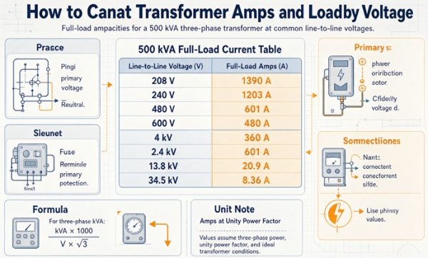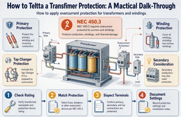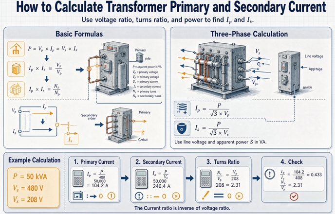
Three phase current is kVA times 1,000 divided by 1.732 times line voltage. Single phase leaves the 1.732 out. That is the whole formula. The rest of the job is knowing which voltage, which side, and which of the five currents you need, because one 1,000 kVA unit carries 41.8 amps at 13.8 kV and 1,203 amps at 480 volts.
Every page that ranks for this question gives you the formula, and most of them give you a table too. That part is settled and you can have it in the next two paragraphs. What none of them do is tell you that a single transformer has five different amp values attached to it, that four of them are correct, and that using the wrong one is how a feeder ends up sized for a third of the load it will carry. So that is what this page is about. The arithmetic comes first because you need it, then the part that actually costs money.
The formula, and the wrong answers you can spot on sight
Two forms cover everything you will do at distribution voltage.
Single phase:  I = (kVA x 1,000) / V
Three phase:   I = (kVA x 1,000) / (1.732 x V)
V in the three phase form is line to line. Always. Even on a 480Y/277 secondary, where 277 volts is sitting right there on the nameplate and looks like the number you should use, you divide by 480. The 1.732 is already accounting for the fact that you have three phases. Using 277 in the three phase form double counts it.
That mistake and two others all land on the same wrong answer, which is the most useful thing on this page.
The 2,083 signature
Take a 1,000 kVA unit at 480 volts. The right answer is 1,202.8 amps.
Now do it two wrong ways. Drop the 1.732 and divide 1,000,000 by 480. You get 2,083.3. Use 277 volts in the three phase form. You get 2,084.3. Those two numbers are one amp apart, and they are the same error wearing different hats, because 480 divided by 1.732 is 277. The formula punishes both mistakes with the same signature.
There is a third path to the same place. Remember that at 480 volts single phase, one kVA is 2.083 amps. Somebody memorizes “2.08 amps per kVA at 480” from a single phase table, applies it to a three phase unit, and gets 2,083. The constant was right. The table was wrong for the job.
So if your answer for a 1,000 kVA unit at 480 volts comes out near 2,083, stop. You are not off by a rounding error. You are off by 73 percent, and every downstream decision inherits it.
| What you get | For 1,000 kVA at 480 V | What you did |
|---|---|---|
| 1,203 A | correct | divided by 1.732 and by 480 |
| 2,083 A | 73 percent high | dropped the 1.732, or used 277 V, or used the single phase constant |
| 3,610 A | 200 percent high | multiplied by 1.732 instead of dividing |
| 962 A | 20 percent low | used 600 V |
| 694 A | 42 percent low | used the delta winding current where the line current belongs |
| 41.8 A | 28.75 times low | used the primary voltage |
The 41.8 entry is the one that hurts. It is the correct primary current for a 13.8 kV unit, and pasting it onto the 480 volt side means a 45 amp feeder feeding a 1,203 amp bus. The transformer will not protect you from that. Neither will the breaker, because a 45 amp breaker on a 1,203 amp load trips the instant you energize, and the crew will spend a day looking for a fault that is actually a decimal point.
One more, and it is the most common of all: using kW where the nameplate says kVA. An 800 kW load at 0.8 power factor is 1,000 kVA, which is 1,202.8 amps. Feed 800 into the formula as though it were kVA and you get 962.3 amps, 20 percent low. The transformer is rated in kVA precisely because the manufacturer does not know your power factor. Do not hand it a number that assumes one.
One transformer, five currents
Here is the part nobody writes down. Put a clamp on a 1,000 kVA unit and you will find five different amp figures in the project documents, all for the same machine, and four of them are right.
| Current | Where the number comes from | 1,000 kVA at 480 V |
|---|---|---|
| Rated full load current | nameplate kVA divided by rated voltage | 1,203 A |
| Load current | the load calculation, nothing to do with the transformer | 850 A |
| Conductor design current | 125 percent of the continuous load | 1,063 A |
| Overcurrent device rating | 125 percent of rated current, rounded to a standard size | 1,600 A |
| Measured current | a clamp meter on the actual feeder | 847 A |
Five numbers, spread from 847 to 1,600 amps, and every one of them belongs on a different line of the same drawing set.
The rated current is a thermal ceiling. It tells you what the winding can carry forever without cooking. It says nothing about what your building draws, and it is not a load. The load current comes out of the load calculation, and on a real project it is usually well under the rating, because nobody buys a transformer at 100 percent of calculated load. The conductor design current is 125 percent of whatever the load is, applied to the conductor and not to the transformer. The device rating is 125 percent of the transformer rating under one row of Article 450, which is why it is bigger than everything else on the list. And the measured current is whatever the building is doing at the moment you put the clamp on, which will not match any of the other four.
The failure mode is mixing them. Size the conductor from the rated current and you have built a feeder for a load that does not exist. Size it from the load current without the 125 percent and you have built a feeder for a continuous load at 100 percent, which is a code violation and a warm conductor. Size the device from the load current and it trips on inrush. Size the CT from the load current and your metering reads high forever.
Write the five columns on the drawing before you calculate anything. Then the calculation has a destination.
A 1,000 kVA unit, both sides, in full
Take a 13,800 volt to 480Y/277 volt unit, 1,000 kVA, and run it out completely. This is the example that shows where every number comes from.
Primary
1,000 kVA times 1,000 is 1,000,000 volt amps. The primary is 13,800 volts line to line, three phase.
1,000,000 divided by 1.732 is 577,367. Divided by 13,800 is 41.84 amps.
At 13.8 kV, about 42 amps. That is a small cable, a 15 kV class termination, and a primary device in the 50 to 60 amp range depending on which row of the protection table applies. Nothing about the primary side of a 1,000 kVA unit is physically large.
Secondary
Same 1,000,000 volt amps. Secondary is 480 volts line to line.
1,000,000 divided by 1.732 is 577,367. Divided by 480 is 1,202.81 amps.
At 480 volts, 1,203 amps. That is four sets of 500 kcmil copper, or three sets of 1,000 kcmil, or a busway. It is a switchboard with a 1,600 amp main. It is, in practical terms, the entire electrical room.
The two numbers are the same transformer, the same core, the same tank, seen from two ends. The insulation on the primary side is designed for 13.8 kV and carries 42 amps. The insulation on the secondary side is designed for 600 volts and carries 1,203 amps. Voltage buys you current, and the exchange rate is fixed.
Where 28.75 comes from
1,203 divided by 41.84 is 28.75. That is exactly 13,800 divided by 480. The current ratio is the line voltage ratio, every time, and it is worth checking your answer against it because it catches arithmetic errors instantly.
Do not confuse it with the turns ratio. For this unit the winding ratio is 13,800 divided by 277.1, which is 49.8. That is the ratio a turns ratio tester reads in single phase mode, and it is a real number about the windings. It is not the number you use for a feeder. Line current ratio uses line voltage on both sides, and on a delta-wye unit the two ratios differ by exactly 1.732. If you compute secondary current from the turns ratio you get 41.84 times 49.8, which is 2,084 amps, and there is that signature again.
Why the secondary is always bigger
A step down transformer puts more current on the low voltage side, and the multiple is the voltage ratio. 13,800 to 480 is 28.75 times. 480 to 208 is 2.31 times. 480 to 120 is 4 times.
This is not a property of transformers. It is a property of power. If the product of voltage and current is constant and you cut one by a factor, the other goes up by the same factor. The transformer is just a device that lets you choose which side of that trade you want.
Two consequences matter on a project.
The first is that the low voltage side is always the expensive side, and it is expensive faster than people expect. A 480 to 208 step down at 1,000 kVA gives 2,776 amps on the secondary. That is 2.31 times the current, 2.31 times the voltage drop in the same conductor, and 5.33 times the resistive loss, because loss goes as current squared. Nobody puts a second tier of distribution in because they like transformers. They do it because 208 volt feeders at 2,776 amps are unaffordable.
The second is that a step up unit runs the same numbers backwards, and crews get confused by it. Take that identical 1,000 kVA machine and feed it from the 480 side. Now 1,203 amps goes in and 41.84 amps comes out at 13.8 kV. It is the same transformer with the leads swapped. The current on the side with the higher voltage is always the smaller one, no matter which way the power is flowing.
The constants worth keeping in your head
You will do this often enough that dividing by 1.732 every time is a waste. One kVA is a fixed number of amps at any given voltage, and six of those constants cover most of a career.
| System | Amps per kVA | 1,000 kVA gives |
|---|---|---|
| 120 V single phase | 8.333 | 8,333 A |
| 240 V single phase | 4.167 | 4,167 A |
| 480 V single phase | 2.083 | 2,083 A |
| 208 V three phase | 2.776 | 2,776 A |
| 240 V three phase | 2.406 | 2,406 A |
| 480 V three phase | 1.203 | 1,203 A |
| 600 V three phase | 0.962 | 962 A |
| 4,160 V three phase | 0.1388 | 139 A |
| 13,800 V three phase | 0.0418 | 41.8 A |
| 34,500 V three phase | 0.0167 | 16.7 A |
Two things to notice. The 480 volt single phase constant is 2.083, and the three phase constant is 1.203, and 2.083 divided by 1.203 is 1.732. That is the only difference between them. And the medium voltage constants are small enough that a 2,500 kVA unit at 34.5 kV carries 41.8 amps, which is about the same as the 480 volt secondary of a 35 kVA unit. High voltage distribution exists to make current disappear.
Here is the same thing as a table, for the standard ratings you will actually see quoted. Three phase, line to line.
| kVA | 208 V | 240 V | 480 V | 600 V |
|---|---|---|---|---|
| 15 | 41.6 | 36.1 | 18.0 | 14.4 |
| 30 | 83.3 | 72.2 | 36.1 | 28.9 |
| 45 | 124.9 | 108.3 | 54.1 | 43.3 |
| 75 | 208.2 | 180.4 | 90.2 | 72.2 |
| 112.5 | 312.3 | 270.6 | 135.3 | 108.3 |
| 150 | 416.4 | 360.8 | 180.4 | 144.3 |
| 225 | 624.5 | 541.3 | 270.6 | 216.5 |
| 300 | 832.7 | 721.7 | 360.8 | 288.7 |
| 500 | 1,387.9 | 1,202.8 | 601.4 | 481.1 |
| 750 | 2,081.8 | 1,804.2 | 902.1 | 721.7 |
| 1,000 | 2,775.7 | 2,405.6 | 1,202.8 | 962.3 |
| 1,500 | 4,163.6 | 3,608.4 | 1,804.2 | 1,443.4 |
| 2,000 | 5,551.4 | 4,811.3 | 2,405.6 | 1,924.5 |
| 2,500 | 6,939.3 | 6,014.1 | 3,007.0 | 2,405.6 |
These are arithmetic, not selections. A 500 kVA unit at 208 volts delivers 1,387.9 amps of current capability, and that is not the same statement as “you may put 1,388 amps of load on it”, because the conductor and the device have their own rules. The table answers one question and it is the first one, not the last one.
Two ladders, and why 112.5 kVA exists
Standard transformer ratings come in two separate lists, and they are not the same list.
| Three phase | Single phase |
|---|---|
| 15, 30, 45, 75, 112.5, 150, 225, 300 | 15, 25, 37.5, 50, 75, 100, 167, 250 |
| 500, 750, 1,000, 1,500, 2,000, 2,500 | 333, 500, 667, 833 |
Read the two columns together and the odd numbers stop being odd. Every three phase rating up to 300 kVA is exactly three times a single phase rating. 15 times 3 is 45. 25 times 3 is 75. 37.5 times 3 is 112.5. 50 times 3 is 150. 75 times 3 is 225. 100 times 3 is 300.
That is where 112.5 comes from. It is 3 times 37.5. It is not a coincidence about panelboard sizes, and it is not a manufacturer’s marketing choice. It is the single phase ladder multiplied by three, which is what you get when you build a three phase bank out of three identical single phase units. A 112.5 kVA three phase transformer is the same iron as three 37.5 kVA single phase units, and the rating is printed that way because that is how it was designed.
The relation only holds to 300 kVA. Push past it and rounding starts: 500 divided by 3 is 166.7, and the single phase ladder has 167, so a 500 kVA three phase unit pairs with a 167 kVA single phase unit and the product is 501, not 500. 750 divided by 3 is 250 exactly, so that one is clean. 1,000 divided by 3 is 333.3, and the single phase ladder has 333, and 333 times 3 is 999.
Which brings up the thing to actually watch for.
200 kVA is not a size
The three phase ladder goes 150, then 225. There is no 200 between them.
You can buy a 200 kVA transformer. Somebody will build one. It is not a stock rating, it is not on the ladder, and a quote for it will reflect that in price and in lead time. If your load calculation says 190 kVA, the answer is 225 kVA, and the person who writes 200 kVA on the requisition has created a six week delay to save nothing.
The same trap exists at 400 and 800 kVA three phase. Neither is standard. The ladder has 500 and 750 and 1,000, and it skips the round numbers that feel natural, which is why so many first drafts of a one line have a 600 kVA transformer on them.
When the nameplate prints four answers
Not every nameplate gives you one kVA and two voltages. A dual voltage unit gives you a small table, and every row in it is correct.
Take a 37.5 kVA single phase unit with a 480 by 240 volt primary and a 240 by 120 volt secondary. That is one transformer with two primary windings and two secondary windings, and you connect them in series or in parallel depending on the system.
| Connection | Terminal voltage | Full load current |
|---|---|---|
| Primary windings in series | 480 V | 78.1 A |
| Primary windings in parallel | 240 V | 156.2 A |
| Secondary windings in series | 240 V | 156.2 A |
| Secondary windings in parallel | 120 V | 312.5 A |
Four currents, one machine, 37.5 kVA throughout. The formula never changed. What changed is which voltage you feed it.
The two 156.2 entries are not a typo. At 240 volts the primary in parallel and the secondary in series carry the same current, because the winding ratio at that point is one to one. If a table like this shows the same number twice, check the voltages before you assume somebody copied a cell.
The trap is that the plate does not always make the pairing obvious. The primary series row is 78.1 amps and the primary parallel row is 156.2, a factor of two, and if you land the windings in parallel on a 480 volt system you have put 480 volts across a 240 volt winding. That is not a calculation error, it is a connection error, and it is also the reason the connection diagram belongs on the drawing next to the current.
Three phase dual voltage primaries behave the same way with one more twist. A 13,800 by 6,900 volt primary on a 1,000 kVA unit is 41.8 amps in series and 83.7 in parallel. The winding current inside the delta at 13,800 volts is a third number again, 24.1 amps, because the winding sees neither terminal voltage. Three currents from one nameplate, and only one of them belongs on the feeder schedule.
So read the plate for the connection, not just for the kVA. If the unit has more than one voltage per winding, write the connection you are building next to the current before you do anything else.
Where the formula quietly stops working: taps
The formula uses a voltage. If the voltage changes, the current changes, and on a transformer with taps the voltage does change.
Take the same 1,000 kVA unit with a standard four tap arrangement at plus and minus 2.5 percent, so five positions from 105 percent to 95 percent of 13,800 volts. Put 13,800 volts on the incoming line and move the tap.
| Tap | Primary rated V | Secondary at 13.8 kV in | Current for 1,000 kVA | Capability at rated current |
|---|---|---|---|---|
| 105 percent | 14,490 | 457.1 V | 1,263.0 A | 952 kVA |
| 102.5 percent | 14,145 | 468.3 V | 1,232.9 A | 976 kVA |
| 100 percent | 13,800 | 480.0 V | 1,202.8 A | 1,000 kVA |
| 97.5 percent | 13,455 | 492.3 V | 1,172.7 A | 1,026 kVA |
| 95 percent | 13,110 | 505.3 V | 1,142.7 A | 1,053 kVA |
Two questions live in that table and they have different answers.
Constant kVA against constant current
If your load is a constant 1,000 kVA, then at the 105 percent tap it needs 1,263 amps, which is 5 percent above what the winding is rated to carry forever. The transformer did not get smaller. Your load got bigger in amp terms.
If instead you hold the winding at its rated 1,203 amps, then at 457 volts the unit delivers 952 kVA, not 1,000. The winding is the limit, and 952 kVA is the honest rating of that machine at that voltage. The core is actually running 5 percent below rated flux and is slightly cooler than it would be at 480 volts.
For a submittal, the second answer is the one that matters, because the nameplate kVA is a rating at the nameplate voltage. Move the voltage and the rating moves with it. A 1,000 kVA transformer on the 105 percent tap, with the utility delivering nominal, is a 952 kVA transformer. That is a 48 kVA loss you did not pay for and will not see on any document.
The 12,470 mistake
Now the version that shows up on real projects. A 13,800 volt nameplate unit installed on a 12,470 volt system, tap left at 100 percent.
Secondary voltage is 480 times 12,470 divided by 13,800, which is 433.7 volts. Capability at the rated 1,203 amps is 903.6 kVA. Your 1,000 kVA transformer is now a 904 kVA transformer, and a load that genuinely needs 1,000 kVA will demand 1,331 amps, which is 110.7 percent of rated current, continuously, on a winding that was designed for 100 percent.
Nobody catches this with the formula, because the formula never gets run on the actual voltage. It gets run once, at the nameplate voltage, and then the number goes on the drawing and stays there for twenty years.
Run it at the measured voltage. If the secondary bus sits at 470 volts instead of 480, the current for the same kVA is 2.1 percent higher, and if it sits at 492 the current is 2.4 percent lower. Neither is a crisis. Both make a difference when you are within 2 percent of a device rating.
Where it stops working completely: autotransformers
Everything above assumes two windings that are not connected to each other. An autotransformer breaks that assumption, and the formula stops describing the machine.
A 3.33 kVA unit carrying 20 kVA
You need 200 volts from a 240 volt supply, for a 20 kVA load.
As an isolation transformer you would buy 20 kVA. Primary current 20,000 divided by 240 is 83.3 amps, secondary 20,000 divided by 200 is 100 amps, and the core has to be built for 20 kVA.
Wire the same job as an autotransformer and you buy a 3.33 kVA unit. Here is what happens inside it. The series section sits between the supply and the tap and carries the full primary current, 83.3 amps, across 40 volts. That is 3,333 volt amps. The common section sits across the 200 volt output and carries the difference between the load current and the primary current, which is 100 minus 83.3, or 16.7 amps. That is also 3,333 volt amps. Both sections are at the same 3.33 kVA, which is why the nameplate says 3.33 kVA, and the terminals pass 20 kVA.
The line currents did not change. Primary is still 83.3 amps, secondary still 100 amps, because power is conserved at the terminals.
What changed is the number you would compute from the nameplate. Read 3.33 kVA off the plate, run the formula, and you get 3,333 divided by 240, which is 13.9 amps. The actual primary current is 83.3 amps. The nameplate kVA understates the line current by a factor of six, and six is exactly 240 divided by 40, the ratio of the supply voltage to the voltage being dropped.
That is the failure mode in one line. Somebody reads a small kVA on a buck-boost unit, sizes the feeder from it, and installs a 15 amp circuit on a 100 amp load. The transformer is fine. The wire is not.
The general rule: for an autotransformer, the nameplate rating describes the windings, and the throughput is the nameplate times the ratio of the supply voltage to the voltage difference. 3.33 kVA times 240 divided by 40 is 20 kVA. Same machine, six times the load.
The three phase version does not scale the same way
Take a 480 volt system, a 400 volt load, 300 kVA.
Load current is 300,000 divided by 1.732 times 400, which is 433 amps. Primary current is 300,000 divided by 1.732 times 480, which is 361 amps.
The transformed kVA is 80 volts of difference times 433 amps times 1.732, which is 60.0 kVA. So a 60 kVA buck-boost bank carries 300 kVA, a ratio of 5.0.
Compare that with the single phase case, where the ratio was the voltage ratio, 240 over 40, which is 6.0. Same idea, different number, because the three phase buck kVA uses the line to line difference and the line current with a 1.732 in it, and the exact multiplier depends on whether the buck bank is wye or delta connected. Which is the practical point: do not scale a three phase buck-boost from the single phase rule. Use the manufacturer’s table for the connection you are building, and check the winding current, not the throughput, against the nameplate.
For anyone specifying one of these, the question to ask the supplier is not “what kVA do I need”. It is “what is the primary line current at this ratio, and what is the winding current”. Those are the two numbers the feeder and the device have to survive, and neither one is the number printed on the plate.
Three more places the number moves
Losses make the primary slightly high
The formula assumes the transformer is ideal, so kVA in equals kVA out. A real unit has losses, and the primary has to supply them.
At 99.1 percent efficiency, which is a realistic full load figure for a 1,000 kVA distribution unit, the primary carries 1,202.8 divided by 0.991, which is 1,213.7 amps. That is 0.9 percent above the ideal number. At 98.5 percent it is 1.5 percent, and at 98 percent it is 2 percent.
Small enough to ignore for a conductor, which has margin anyway. Not small enough to ignore if you are setting a relay to within 1 percent, or if you are comparing a calculated loss figure against a meter reading and the numbers will not close.
Unbalance hides in the average
A 1,000 kVA unit reading 1,400, 1,100 and 1,110 amps has an average of 1,203, which is exactly rated. It also has one phase at 116.4 percent of rated current, and that phase is the one that decides the winding temperature.
Three phase current calculation assumes a balanced load. Real buildings are not balanced, and a wye secondary feeding single phase panelboards will run 10 to 20 percent spread as a matter of course. If you are loading a transformer past about 85 percent of nameplate, look at the highest phase, not the average. The average is the number that makes the report look fine.
Two units in parallel do not share evenly
Put two 500 kVA units on the same bus and each one carries 500 kVA, right up until they do not.
Load sharing between paralleled transformers is inverse to impedance. Two 500 kVA units at 5.75 and 6.5 percent impedance, carrying 1,000 kVA total, split 530.6 and 469.4. The lower impedance unit takes more, and it takes it in proportion to the other unit’s impedance.
The consequence: that pair runs out of capacity at 942 kVA, not 1,000, because the 5.75 percent unit hits its rating first. Six percent of the bank is unusable, and it is invisible on the nameplate, because both units say 500 kVA.
If you need the full 1,000, order matched impedances and check them on the test report. The nameplate kVA does not tell you how the bank will share.
When the clamp meter disagrees with the arithmetic
You calculated 1,203 amps, you put a clamp on the feeder, and you read 1,180. Or 1,255. Both are normal, and the size of the gap tells you what is causing it.
| Reading against calculated | Size | Most likely cause |
|---|---|---|
| 2 to 5 percent low | small | supply voltage is above nominal, so the same kVA needs fewer amps |
| 3 to 6 percent high | small | harmonic content, a true RMS meter reads above the fundamental |
| one phase 10 to 20 percent above average | medium | unbalance, single phase load on a wye secondary |
| 5 to 10 percent high at light load | medium | the transformer is drawing more than the load, losses plus magnetizing current |
| 20 percent low | large | you used kW where the nameplate says kVA |
| 73 percent high | large | you dropped the 1.732 or used the line to neutral voltage |
| 28.75 times low | large | you used the primary voltage on the secondary |
Three of these are measurement realities and three are calculation errors, and they are separated by size. Small gaps are physics. Gaps over 20 percent are almost always your arithmetic, not the building.
The harmonic entry is worth a number. At 30 percent total harmonic distortion, which is not unusual on a feeder full of variable frequency drives, a true RMS meter reads 1,255.8 amps where the fundamental is 1,202.8. That is 4.4 percent high, and the extra current is real, and it heats the winding. The formula computed a sinusoidal current. The building is not delivering one.
The voltage entry cuts the other way and is bigger than people think. A utility running 2 percent high puts the secondary at 490 volts, and a constant kVA load then draws 1,179 amps instead of 1,203. That is a 2 percent margin you did not plan for, and it disappears the day the utility adjusts the tap changer on the substation.
What you do with the number once you have it
The calculation is the easy part. Three things consume it.
Conductor
Take the load current, apply 125 percent for a continuous load, and size the conductor to that. Note that this uses the load current, not the transformer rated current. A 1,000 kVA unit loaded to 850 amps needs conductor for 1,063 amps, not for 1,504.
But if you are sizing the feeder from the transformer rating, because the load is not known yet or because the owner wants the full capability delivered to the panel, then 1,202.8 times 1.25 is 1,503.5 amps, and the conductor set is four runs of 500 kcmil at 380 amps each, which is 1,520, or three runs of 1,000 kcmil at 545 each, which is 1,635. Three runs of 750 kcmil gives 1,425 and is short. The set count is the answer, not the wire size, and at this level the cost is in the terminations and the conduit, not the copper.
Above 800 amps there is no next size up allowance on the conductor, so the ampacity has to actually reach the number. That is a code detail with real cost attached, and it is why the four run answer is not negotiable down to three and a half.
Device
The device is 125 percent of rated current under the primary only row, or 250 percent under the primary and secondary row, and the arithmetic for that lives in Article 450 rather than here. One practical note: 1,202.8 times 1.25 is 1,503.5, and the next standard device is 1,600. That is the 1,600 amp main on the switchboard, and it is why the switchboard is bigger than the transformer.
The thing to get right is which current the device is sized from. It is the rated current, always, not the load current. A device sized from an 850 amp load is a 1,000 or 1,100 amp device, and it will nuisance trip on inrush every time the utility recloses.
CT ratio
For metering and protection you need a CT that covers the rated current without saturating and without pinning the meter at full scale.
For 1,203 amps, the choices are 1,200:5 and 1,500:5. A 1,200:5 CT is a 240:1 ratio, and at 1,203 amps the secondary current is 5.01 amps, which is nominally 100.3 percent of the 5 amp rating. That is fine, because CTs carry continuous overload well past nominal, but it does mean the meter sits at the top of its scale at full load with nowhere to go for a short time overload.
A 1,500:5 CT is a 300:1 ratio, and at 1,203 amps it reads 4.01 amps, which is 80 percent of nominal. You get headroom, and you give up resolution at light load. On a building that runs at 40 percent load most of the year, 80 percent of nominal at full load is the right trade, because 40 percent load on a 1,500:5 CT still reads 1.6 amps, which is plenty for a modern meter.
What you do not do is install a 1,000:5 CT because the load calculation said 850 amps. It reads 4.25 amps at the load you designed for, and the first time somebody runs the building at full capacity the CT is at 120 percent and the meter is over range.
The worksheet
Nine lines, in this order. It fits on a sticky note and it catches everything above.
1  kVA                     from the nameplate, never from kW
2  Primary volts L-L       nameplate, not the system nominal
3  Secondary volts L-L     nameplate, not the system nominal
4  I primary   = kVA*1000 / (1.732 * Vp)
5  I secondary = kVA*1000 / (1.732 * Vs)
6  Check: Is / Ip must equal Vp / Vs
7  Tap and actual voltage  recalculate at the voltage you will really have
8  Load current            from the load calc, this is a different number
9  Design current          load * 1.25 for conductor, rated * 1.25 for device
Line 6 is the one that saves you. If the ratio does not come out to the voltage ratio, you have an arithmetic error somewhere, and you find it in ten seconds instead of after the switchboard is built.
Line 7 is the one that saves the project. It is the line nobody writes, and it is where the 952 kVA and the 904 kVA live.
FAQ
What is the formula for transformer primary and secondary current?
Three phase is kVA times 1,000 divided by 1.732 times line to line voltage. Single phase is kVA times 1,000 divided by voltage. Run it once with the primary voltage and once with the secondary voltage. The transformer kVA is the same in both, which is why the low voltage side always carries more current and the ratio between the two sides is exactly the ratio of the voltages.
Why is the secondary current higher than the primary current?
Because the transformer trades voltage for current and the product stays constant. A 13,800 to 480 volt unit has a 28.75 to 1 voltage ratio, so the secondary current is 28.75 times the primary current. On a 1,000 kVA unit that is 41.8 amps in and 1,203 amps out. Nothing is gained or lost in the exchange beyond the losses, which are small.
Do I use line to line or line to neutral voltage?
Line to line, always, in the three phase formula. On a 480Y/277 secondary the nameplate shows both 480 and 277, and 277 is the line to neutral value. Dividing by 277 in the three phase form gives 73 percent too much current, and it lands on almost exactly the same wrong answer you get by dropping the 1.732 entirely.
How many amps is a 1,000 kVA transformer?
It depends on the voltage, and that is the whole point. At 480 volts three phase it is 1,203 amps. At 208 volts it is 2,776. At 600 volts it is 962. At 13,800 volts it is 41.8. Same transformer, same kVA, and the current varies by a factor of 66 across those four voltages. Always state the voltage with the amps or the number means nothing.
Why did I get 2,083 amps instead of 1,203?
You either dropped the 1.732 or used 277 volts instead of 480, and both land within one amp of each other because 480 divided by 1.732 is 277. A third path is using the single phase constant of 2.083 amps per kVA at 480 volts on a three phase unit. All three are 73 percent high, and every device and conductor downstream inherits the error.
Does a tap change the secondary current?
Yes, and it changes the rating too. On a 1,000 kVA unit, moving to the 105 percent tap with 13,800 volts applied puts the secondary at 457 volts. A constant 1,000 kVA load then needs 1,263 amps, which is 5 percent over the winding rating. Held at the rated 1,203 amps, the unit delivers 952 kVA. The nameplate rating only applies at the nameplate voltage.
Can I calculate autotransformer current from the nameplate kVA?
No, and this is the most dangerous entry on the page. A 3.33 kVA buck-boost wired as an autotransformer to drop 240 volts to 200 carries 20 kVA. Its primary current is 83.3 amps, not the 13.9 amps the nameplate kVA suggests. The plate describes the windings, not the throughput, and the ratio between them is the supply voltage divided by the voltage being dropped.
What current do I use to size the breaker?
The rated current, not the load current. For a 1,000 kVA unit at 480 volts that is 1,203 amps, and the primary only allowance of 125 percent gives 1,504, which rounds up to a 1,600 amp device. Sizing from an 850 amp load gives a 1,100 amp device that will trip on magnetizing inrush every time the transformer is energized.
Why does the clamp meter read higher than my calculation?
Usually harmonics. A true RMS meter includes harmonic current that the formula does not model, and at 30 percent total harmonic distortion it reads about 4.4 percent above the fundamental. Voltage works the other way: a supply running 2 percent high means the same kVA load draws 2 percent fewer amps. Gaps under 10 percent are usually physics. Gaps over 20 percent are usually arithmetic.
What is the primary current of a 75 kVA transformer at 480 volts?
90.2 amps, three phase. The secondary current depends on the secondary voltage: 208.2 amps at 208 volts three phase, 312.5 amps at 240 volts single phase, and 625 amps at 120 volts single phase. The 90.2 figure is the one that sizes the primary feeder and the primary device on a 480 volt three phase unit.
Why is 112.5 kVA a standard size?
Because it is three times 37.5 kVA, and 37.5 is on the single phase ladder. Every three phase rating up to 300 kVA is exactly three times a single phase rating, which is what you get when a three phase unit is built from three identical single phase cores. 15 times 3 is 45, 25 times 3 is 75, 37.5 times 3 is 112.5, and 50 times 3 is 150.
What is the winding current inside a delta?
Line current divided by 1.732. On a 1,000 kVA 480 volt delta winding the line carries 1,203 amps and each winding carries 694 amps. That matters for a DC resistance test, a winding temperature sensor, or any calculation about the conductor inside the tank, because those see the winding current and not the line current.
Free: Transformer Specification Checklist
The exact RFQ sheet our engineers use — send it and get a quoted proposal within 24h.
Download checklist