A 500 kVA transformer carries 601 amps at 480 volts three phase, 1,203 amps at 240, 1,388 amps at 208 and 20.9 amps at 13.8 kV. The kVA never changes. Amps are 500,000 divided by 1.732 times the voltage, so the same unit is a 601 amp machine or a 21 amp machine depending on which winding you clamp.
That paragraph answers the question you typed. It is also where every page in the top ten stops, and stopping there is why people call us with a 601 amp number on a drawing and an 800 amp switchboard already ordered. The rated current is a thermal limit on the winding. It is not the current you buy cable for, and it is not the current a breaker gets set to. Those are three different numbers, and only the first one is 601.
So this page does the whole ladder. The plain table first, because you may only need that. Then the two numbers that come after it, the four ways the arithmetic goes wrong, and the reason a 500 kVA unit at 208 volts is a completely different project from the same unit at 480.
The short answer, in one table
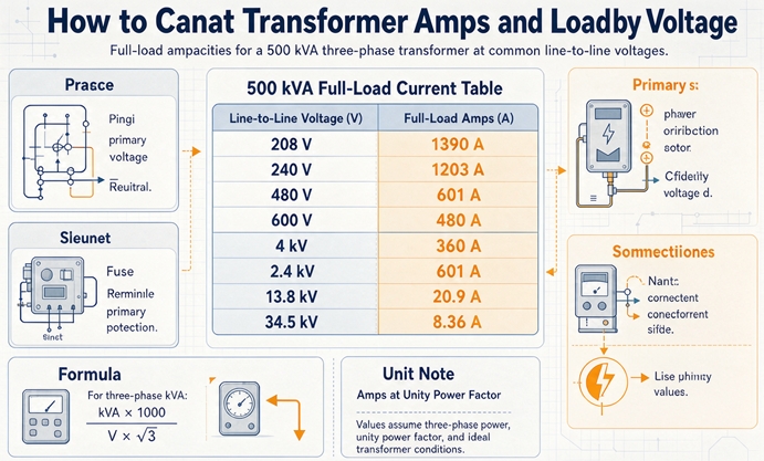
500 kVA three-phase full-load current, rounded, with line-to-line voltage on the left and rated current on the right.
| Voltage (line to line) | Full-load amps |
|---|---|
| 208 V | 1,388 A |
| 240 V | 1,203 A |
| 380 V | 760 A |
| 400 V | 722 A |
| 415 V | 696 A |
| 440 V | 656 A |
| 460 V | 628 A |
| 480 V | 601 A |
| 600 V | 481 A |
| 4,160 V | 69 A |
| 13,800 V | 21 A |
| 34,500 V | 8.4 A |
Read it as a curve, not as twelve facts
Read the table as a single curve, not as twelve facts. Double the voltage and you halve the amps. 208 to 416 is not on the list, but 208 to 4,160 is, and 1,388 divided by 69 is 20.0, which is exactly the ratio of the two voltages. Every row is the same 500,000 volt amps wearing a different voltage.
Two rows that get misread
Two rows deserve a note before you use them.
The 208 V row is 1,388 A, not 1,203 A. Somebody who remembers “500 kVA is about 600 amps” and then takes a 208 V job is off by a factor of 2.3, and the switchboard they ordered will not land.
The 34,500 V row is 8.4 A, and 8.4 is a small enough number that people write “8 A” and move on. On the primary of a 34.5 kV unit, 0.4 amps of rounding is 5 percent of the current, which is the entire accuracy budget of a protective relay setting. Keep one decimal below 100 amps.
Rounded numbers hide the one you need
Take the 480 V row. The exact value is 601.4 A, and the table says 601. If you multiply 601 by 1.25 you get 751.3 and if you multiply 601.4 by 1.25 you get 751.8. Both round to a 752 A design current. Both land on an 800 A device. So for this unit, the rounding costs you nothing.
Now take a 208 V unit. Exact is 1,387.9 A and 125 percent is 1,734.9 A. If you had rounded down to 1,388 first, 125 percent is 1,735.0. Same answer again. The rounding only bites when the result sits within a few amps of a standard device rating, and at 500 kVA the standard ratings are far enough apart that it does not. Use the exact number anyway, because your spreadsheet will eventually be pointed at a size where it does.
601 amps is the rating, not the number your feeder gets sized on
Here is the gap that costs money. A 500 kVA, 480 V transformer has three separate amp values attached to it in a normal set of drawings, and they are 601, 752 and 800.
| What it is | Where it comes from | Value at 480 V |
|---|---|---|
| Rated full-load current | 500,000 divided by 1.732 divided by 480 | 601 A |
| Conductor design current | 125 percent of the load, continuous duty | 752 A |
| Overcurrent device rating | 125 percent of rated current, next standard size up | 800 A |
The 601 A is a thermal ceiling. It is the current the winding can carry indefinitely at rated temperature rise without aging faster than the insulation system allows. It is stamped on the nameplate because the factory tested for it. It is not a load, and nothing in a building draws exactly 601 A on purpose.
The 752 A is the number the cable gets sized on. Continuous loads get 125 percent under NEC 215.2 for feeders and 230.42 for services, and the transformer’s own feeder is a continuous load by any reasonable reading because it runs for three hours or more. 601.4 times 1.25 is 751.8. That is the number you hand to the cable schedule.
The 800 A is the number the breaker gets, and it comes from a different rule. Article 450 says the secondary device can sit at 125 percent of rated current, and NEC 240.6(A) says you then move up to the next standard rating. 751.8 is not a standard rating. 800 is. So 800 it is.
Three numbers, one machine, three different lines on one drawing. Getting them in the right order is the whole job. Put 601 A on a feeder and you have built for 80 percent of the load. Put 752 A on a breaker and you have no standard frame to buy. Put 800 A on the cable and you have a conductor that cannot carry the device protecting it.
Why the device is larger than the thing it protects
An 800 A breaker on a transformer rated 601 A looks wrong until you remember what the breaker is for. It is not there to protect the winding from 650 amps of overload. The winding has its own thermal margin built into the kVA rating, plus a service factor on the insulation system, plus an overload curve that the manufacturer publishes. The breaker is there to clear a fault and to hold through inrush.
Inrush is the reason the number is 125 percent and not 105 percent. A 500 kVA unit at 480 V pulls somewhere between 8 and 12 times rated current for about a tenth of a second when you close the primary. That is 4,800 to 7,200 amps, briefly. An 800 A thermal-magnetic breaker with a magnetic trip set at 10 times its rating sees 8,000 A and holds. A 601 A breaker set the same way sees 6,010 A and might not. The 125 percent is not protecting the transformer from the load. It is buying the breaker enough headroom to ignore the transformer starting up.
The formula, and the 1,042 signature that catches the two common mistakes
Three phase current is kVA times 1,000 divided by 1.732 times line-to-line voltage. Single phase drops the 1.732. That is all of it, and there is nothing to add except the discipline of using the right voltage in the right place.
Three phase:  I = (kVA x 1,000) / (1.732 x V line-to-line)
Single phase: I = (kVA x 1,000) / V
For 500 kVA at 480 V three phase, that is 500,000 divided by 831.4, which is 601.4 A. The 831.4 is 1.732 times 480, and it is the only number in the calculation you can get wrong without noticing.
Two different mistakes, one identical wrong answer
Here is the part worth memorizing. At 480 volts, two separate errors both produce 1,042 amps.
Drop the 1.732 and divide 500,000 by 480. You get 1,041.7.
Use 277 volts, the line-to-neutral voltage printed right next to 480 on a 480Y/277 nameplate, in the three-phase formula. You get 1,042.1.
Those are half an amp apart. They are the same error wearing two hats, because 480 divided by 1.732 is 277. The formula punishes both with one signature.
There is a third road to the same place. At 480 volts single phase, one kVA is 2.083 amps, so 500 kVA is 1,041.7 A. That is a correct answer to a different question. Somebody reads a single-phase table, carries the constant over to a three-phase unit, and gets 1,042.
So if your answer for a 500 kVA, 480 V transformer comes out near 1,042, stop. You are not off by a rounding error. You are 73 percent high, and every conductor, breaker and lug downstream inherits it.
| Answer | Error | How you got there |
|---|---|---|
| 601 A | correct | divided by 1.732 and by 480 |
| 1,042 A | 73 percent high | dropped the 1.732, or used 277 V, or used the single-phase constant |
| 347 A | 42 percent low | used the delta winding current where the line current belongs |
| 481 A | 20 percent low | used 600 V |
| 21 A | 28.75 times low | used the primary voltage |
| 939 A | 56 percent high | applied the 125 percent twice |
The 351 A entry needs a word, because it is subtle. Inside a delta winding, each coil carries line current divided by 1.732. On a 601 A line, the coil current is 347 A. If you are selecting a conductor between the transformer and the switchboard, you want the line current, not the coil current. The coil number belongs in a winding resistance test or a winding temperature calculation, nowhere near a cable schedule.
The 751 A entry is the one we see most often in review. Someone applies 125 percent for continuous load, then someone else applies 125 percent again for the device, and the third person applies it once more “for margin.” Three 125 percents is 195 percent, which is 1,173 A, and now the 800 A switchboard on order is the wrong switchboard.
One more, and it is quiet: using kW where the nameplate says kVA. A 500 kVA unit at 0.8 power factor delivers 400 kW. Feed 400 into the formula as though it were kVA and you get 481 A, which is 20 percent low and happens to be the correct answer for a 500 kVA unit at 600 volts. The transformer is rated in kVA because the factory does not know your power factor. Do not hand it a number that assumes one.
500 kVA full-load amps at low voltage, 208 through 600
Everything under 600 volts is Article 450 territory, single-layer insulation, and the voltages your electricians actually see. The current spans a factor of 2.9 across this range, which is why the voltage field on a purchase order matters more than the kVA field.
| Secondary voltage | Connection | Full-load amps | Amps per kVA |
|---|---|---|---|
| 208Y/120 | wye, grounded | 1,388 A | 2.776 |
| 240 | delta | 1,203 A | 2.406 |
| 240/120 | delta, center tapped | 1,203 A | 2.406 |
| 380Y/220 | wye | 760 A | 1.519 |
| 400Y/231 | wye | 722 A | 1.443 |
| 415Y/240 | wye | 696 A | 1.391 |
| 440 | delta | 656 A | 1.312 |
| 460 | delta | 628 A | 1.255 |
| 480 | delta | 601 A | 1.203 |
| 480Y/277 | wye, grounded | 601 A | 1.203 |
| 600Y/347 | wye, grounded | 481 A | 0.962 |
The delta and wye versions of the same voltage carry the same line current. A 480 V delta and a 480Y/277 both move 601 A. The connection changes what the neutral does and what the insulation has to withstand, not the current in the phase conductors.
That trips people up on the 240 V rows. A 240 V delta and a 240/120 V center-tapped delta both carry 1,203 A of line current, and the numbers look identical on a one-line. They are not interchangeable. The center-tapped version gives you 120 V from either outer leg to the center tap, but only at the capacity of that half winding, and the high leg sits at 208 V to ground with a different color code. If the load is 120 V lighting and receptacles, the 240/120 delta will run out of neutral-side capacity long before it runs out of 1,203 A.
The 380, 400, 415, 440 and 460 rows are there because half the world’s drawings land in the US inbox with those numbers on them. A 415Y/240 unit carries 696 A, which is 16 percent more than the 480 V unit at the same kVA. If you substitute a 480 V unit for a 415 V one on a panel schedule built for 415, the current drops to 601 A and the breakers are now oversized by 16 percent. If you go the other way, they are undersized by 14 percent and will nuisance trip.
The 600 volt row is worth a second look
At 600Y/347, the current is 481 A and the 125 percent design current is 601.4 A, which is exactly the full-load current of the 480 V unit. That is a coincidence of arithmetic, not a physical relationship, but it is a useful one: if you are moving a 500 kVA load from 480 to 600 volts, the new design current equals the old rated current. You drop one conductor size and one breaker frame for the same kVA.
The trade is insulation. 600 V class equipment costs more per amp than 480 V class, and 347 V line-to-neutral loads are not the appliances your tenants own. 600 V shows up in Canada, in mining, and in plant distribution where the run is long enough that the current reduction pays for the switchgear. It is not a default.
500 kVA full-load amps on the primary side, 2,400 through 34,500
The primary is where the numbers get small enough to misread. Same 500 kVA, same formula, much larger divisor.
| Primary voltage | Connection | Full-load amps |
|---|---|---|
| 2,400 | delta | 120 A |
| 4,160 | delta | 69 A |
| 4,160Y/2,400 | wye, grounded | 69 A |
| 4,800 | delta | 60 A |
| 7,200 | delta | 40 A |
| 12,000 | delta | 24 A |
| 12,470Y/7,200 | wye, grounded | 23 A |
| 13,200 | delta | 22 A |
| 13,200Y/7,620 | wye, grounded | 22 A |
| 13,800 | delta | 21 A |
| 13,800Y/7,970 | wye, grounded | 21 A |
| 22,900Y/13,200 | wye, grounded | 13 A |
| 24,940Y/14,400 | wye, grounded | 12 A |
| 34,500 | delta | 8.4 A |
| 34,500Y/19,920 | wye, grounded | 8.4 A |
Nothing here exceeds 120 A, which means the primary feeder for a half-megawatt transformer is often a single 1/0 or 2/0 copper run, and the primary device is a fuse in a cutout or a 100 A class breaker. That asymmetry is the whole reason utilities distribute at medium voltage.
The 40 amp answer that belongs to a different transformer
Take the 12,470Y/7,200 row. The line current is 23 A. Somebody reads “7,200” off the nameplate, puts it in the three-phase formula, and gets 40.1 A.
Forty amps is 73 percent high, and it is exactly the right answer for a 7,200 V delta primary. It is the same failure as the 1,042 signature, one voltage level up: the phase voltage went into a formula that wants the line-to-line voltage. On a grounded wye primary, use the line-to-line number, 12,470. If you prefer to work in phase voltage, the formula becomes 500,000 divided by three times 7,200, which gives the same 23 A. Both roads lead to 23. Only the mixed road leads to 40.
That check is worth doing out loud on any wye primary above 5 kV, because a 73 percent error on the primary side is usually invisible. The 40 A fuse you install will not blow on a 23 A load. It will simply fail to protect the transformer, and the failure will show up years later as a burned winding with no explanation.
Primary current and the tap position
A 500 kVA unit typically ships with plus and minus 2.5 percent taps, two above and two below. The taps change the turns ratio, which changes the secondary voltage at a given primary voltage, and the current follows.
Put the unit on a tap that raises the secondary voltage by 2.5 percent and the 480 V secondary becomes 492 V. At the same 500 kVA, the current drops to 587 A. Move two steps the other way and you are at 468 V and 617 A. One 2.5 percent step is worth about 15 amps at 480 volts.
That matters for two reasons. First, a measured secondary current 15 A off the nameplate is not a fault, it is a tap. Second, the amp value you put on a drawing should be the value at nominal voltage, because that is what the device and the cable were selected against. Do not re-rate the feeder for the tap you happen to be sitting on.
The 28.75 to 1 ratio, and what it does to your gear
Divide 601.4 by 20.9 and you get 28.75. That is the voltage ratio of a 13,800 to 480 volt unit, and it is also the current ratio, because kVA is constant on both sides.
Nothing in the transformer changes that. The ratio is set by the turns count on the two windings. A 500 kVA unit with 1,150 primary turns and 40 secondary turns has a 28.75 ratio and behaves exactly as the arithmetic says.
What the ratio does change is the physical size of everything on the two sides. The 13.8 kV side needs 15 kV class insulation, 95 kV or 125 kV BIL bushings, and clearances measured in inches. The 480 V side needs 601 A of copper, which is two sets of 500 kcmil, plus a switchboard with an 800 A frame and a bus that can take a 10 kA fault. The 21 A side costs more per amp by a wide margin. The 601 A side costs more in total.
The ratio is also why a transformer is not a load balancer. If you put 601 A on one phase and 400 A on the other two, the transformer does not average them. It heats on the worst phase, and the kVA you can actually deliver drops below 500. NEMA allows a small voltage unbalance, and current unbalance runs several times the voltage unbalance on a delta-wye unit, so a 2 percent voltage unbalance can produce 8 to 10 percent current unbalance. The 601 A rating assumes balanced.
Amps per kVA, the shortcut that beats the calculator
If you do this work more than once a month, memorize one number per voltage and stop dividing. Amps per kVA is 1,000 divided by 1.732 times voltage, and once you have it, sizing is one multiplication.
| Voltage | Amps per kVA | 500 kVA gives |
|---|---|---|
| 208 V | 2.776 | 1,388 A |
| 240 V | 2.406 | 1,203 A |
| 480 V | 1.203 | 601 A |
| 600 V | 0.962 | 481 A |
| 4,160 V | 0.1388 | 69 A |
| 12,470 V | 0.0463 | 23 A |
| 13,800 V | 0.0418 | 21 A |
| 34,500 V | 0.0167 | 8.4 A |
The 480 V constant is the one to keep. One kVA is 1.203 A, so 500 kVA is 500 times 1.2, which is 600, plus half a percent for the 0.003 you dropped, which is 601. You can do that in your head while somebody is talking.
The constant also runs backward, and that is where it earns its keep. A panel schedule says 800 A at 480 V. Divide 800 by 1.203 and you get 665 kVA, which is not a standard size, so you are buying 750 kVA. A different schedule says 400 A at 208 V. Divide by 2.776 and you get 144 kVA, so 150 kVA, and now you can sanity check the engineer who specified 225 kVA against the actual load.
Two cautions. The constant is for three-phase line current. For single phase, amps per kVA is 1,000 divided by voltage, which at 480 V is 2.083, nearly double the three-phase constant at the same voltage. And the constant assumes the voltage you typed is the voltage the transformer will see, which on a real service is a range, not a number.
The four numbers that hang off 601 amps
Once you have the rated current, four separate decisions follow from it. Each one uses a different multiplier, and mixing them up is how a project ends up with an 800 A breaker on a 400 A cable.
The device
At 480 V, the secondary device is 800 A. That comes from 125 percent of 601.4, rounded up under 240.6(A). It is a device rating, not a setting, and the setting is a separate conversation that belongs to a coordination study.
If the transformer is 13.8 kV to 480 V, the primary device is a different article. Above 600 V, Article 450 gives you up to 300 percent of primary current where the impedance is 6 percent or less, with the next standard rating permitted. 20.9 A times 3 is 62.7, and the next standard E-rated fuse above that is 65E. On the 480 V side you are in the 125 percent world. Two sides, two rules, one transformer.
The conductors
752 A of design current needs copper. At 75 degrees C, 500 kcmil copper carries 380 A, so two sets carry 760 A and that satisfies 752. Barely, and it satisfies it.
| Design current | Copper at 75 C | Sets needed |
|---|---|---|
| 752 A | 500 kcmil, 380 A each | 2 sets, 760 A |
| 752 A | 250 kcmil, 255 A each | 3 sets, 765 A |
| 1,128 A | 600 kcmil, 420 A each | 3 sets, 1,260 A |
| 1,504 A | 600 kcmil, 420 A each | 4 sets, 1,680 A |
| 1,735 A | 500 kcmil, 380 A each | 5 sets, 1,900 A, and not enough |
Two sets of 500 or three sets of 250, same ampacity, different installation. Two sets means two 500 kcmil conductors per phase in one conduit, which is a hard pull, a tight bend radius, and a lug that takes 500 kcmil. Three sets of 250 is easier to pull and easier to terminate, and it costs more in labor and conduit fill. On a 500 kVA job we usually see two sets of 500 for a short run and three sets of 250 when the run is long and the bends are tight.
The last row is the one to remember. At 1,735 A, five sets of 500 gets you 1,900 A, which is more than the 1,735 A design current, so the conductor is fine on ampacity. It is not fine under NEC 240.4(C), which says that above 800 A the conductor must carry the rating of the device protecting it. The device is 2,000 A. Five sets of 500 cannot carry 2,000 A. Six sets can, at 2,280 A, and now you are pulling eighteen 500 kcmil conductors through a switchboard.
That rule is why 208 V at 500 kVA is a different project, and it gets its own section below.
The neutral
On a 480 V delta secondary there is no neutral, and the question does not arise. On a 480Y/277 unit there is, and its size is not automatically the phase size.
For a feeder serving line-to-neutral loads, the neutral carries the imbalance plus the triplen harmonics. On a modern 277 V lighting and office load, third harmonic content adds in the neutral instead of cancelling, and a neutral sized at 100 percent of the phase conductor can run hotter than the phase. The fix is either a full-size or oversized neutral, or a specification that keeps the 277 V load linear. Either way, it is a decision made at design, not at the supply house.
The fault current
The rated current tells you what the transformer delivers on purpose. Divide it by the impedance and you get what it delivers by accident.
| Impedance | Fault current at 480 V | What it means |
|---|---|---|
| 4.0 percent | 15,035 A | 10 kA equipment is not enough |
| 5.0 percent | 12,028 A | 22 kA equipment is comfortable |
| 5.75 percent | 10,459 A | typical 500 kVA value |
| 6.0 percent | 10,023 A | 22 kA equipment is comfortable |
| 8.0 percent | 7,518 A | unusual for this size |
The arithmetic is 601.4 divided by 0.0575, which is 10,459 A. That is a first-cycle, infinite-bus approximation, and it is close enough to pick a switchboard interrupting rating, not close enough to set a relay. For that you need the utility’s available fault current at the primary, the transformer impedance at the tap position, and the motor contribution.
Two practical notes. A 500 kVA unit at 480 V lands near 10.5 kA at standard impedance, so 22 kA switchgear covers it with room and 10 kA switchgear does not. And the impedance you specify is a purchase decision, not a discovery. Ask for 5.75 percent and you get 10.5 kA. Ask for 4 percent on the same kVA and you get 15 kA and a more expensive switchboard, in exchange for slightly better voltage regulation.
The same 500 kVA at 208 volts is a different project
Connect a 500 kVA unit to a 208Y/120 secondary and the current is 1,388 A. Multiply by 1.25 and the design current is 1,735 A. Round up to a standard device and you are at 2,000 A.
Now the conductor. Under 240.4(C), the conductor has to carry 2,000 A. Five sets of 500 kcmil gives 1,900 A and fails. Six sets gives 2,280 A and passes, which is eighteen conductors plus a neutral and a ground in the same pull.
| Secondary | Full-load amps | 125 percent | Device | Conductor sized to the device |
|---|---|---|---|---|
| 208Y/120 | 1,388 A | 1,735 A | 2,000 A | 6 sets of 500 kcmil, or busway |
| 240 delta | 1,203 A | 1,504 A | 1,600 A | 4 sets of 600 kcmil |
| 480Y/277 | 601 A | 752 A | 800 A | 2 sets of 500 kcmil |
| 600Y/347 | 481 A | 601 A | 700 A | 2 sets of 350 kcmil |
Six sets per phase, not five
This is why nobody puts 500 kVA on a 208 V secondary if they can avoid it. The transformer is the same price. The switchboard is not. A 2,000 A switchboard with a 2,000 A main and six parallel sets per phase is a different order of cost from an 800 A switchboard, and the fault current at 208 volts is 2.3 times the 480 volt value for the same kVA, so the switchboard is braced for roughly 24 kA instead of 10.5.
The design that avoids it
The usual design is a 480 V service and a 500 kVA unit, then 480 to 208 step-down transformers distributed near the load, each in the 75 to 150 kVA range, so the 208 V runs stay short and the ampacity stays inside two or three sets. If a client insists on one big 208 V transformer, the honest answer is busway, not cable.
Single phase 500 kVA, where the answer is 2,083
Every table above assumes three phase. A 500 kVA single-phase transformer at 240 volts carries 2,083 A, not 1,203 A. Same kVA, same voltage, 73 percent more current, because there is no third phase to share the load.
| Single-phase voltage | Full-load amps |
|---|---|
| 120 V | 4,167 A |
| 240 V | 2,083 A |
| 277 V | 1,805 A |
| 480 V | 1,042 A |
| 600 V | 833 A |
| 2,400 V | 208 A |
| 4,160 V | 120 A |
| 7,200 V | 69 A |
| 12,470 V | 40 A |
| 13,800 V | 36 A |
Single-phase units at 500 kVA exist, mostly as two-bushing distribution transformers on rural utility lines and as furnace or rectifier transformers in plants. They are not common in commercial service, because at that size the single-phase option costs more copper and delivers a worse voltage balance.
The 2,083 trap
But the number matters even if you never buy one, for two reasons. First, 1,042 A is the value the single-phase formula gives at 480 V, and it is the same value the three-phase formula gives when you forget the 1.732. If you see 1,042 on a drawing for a three-phase unit, the two possibilities are indistinguishable from the number alone, and both are wrong.
Why the two answers collide
Second, 2,083 A is what a 500 kVA single-phase unit delivers at 240 V, and 2,083 is also what you get by dividing 500,000 by 240 without a 1.732 anywhere. The two answers coincide because the single-phase formula has no 1.732 to forget. That is why the single-phase table is a trap for people who work mostly in three phase and a check for people who do not.
Inrush, the amp number that is not on any chart
Rated current is steady state. The current at the instant of energization is a different animal, and it is bigger by an order of magnitude.
A 500 kVA unit at 480 V draws 8 to 12 times rated current for roughly 0.1 seconds when the primary closes. That is 4,811 to 7,217 amps, and it is not a fault. It is the core saturating while the flux wave establishes itself, and it happens every time you energize, including after a brief outage.
| Event | Magnitude | Duration | Governs |
|---|---|---|---|
| Full-load current | 601 A | continuous | conductor ampacity |
| Overload | up to 1,200 A | minutes to hours | winding temperature |
| Inrush | 4,811 to 7,217 A | about 0.1 s | breaker magnetic trip, fuse selection |
| Fault | about 10,500 A | until cleared | equipment interrupting rating |
The inrush number is what sets the instantaneous trip, and it is why a breaker with a magnetic trip at 10 times rating is the usual choice on a transformer feeder. Ten times 800 is 8,000 A, which sits above the 7,217 A worst case and below the 10,459 A fault. That window is narrow, and on a 500 kVA unit it is comfortable. On a 2,000 kVA unit the window closes, and you need a breaker with an adjustable short-time delay or a fuse with a time-current curve shaped for the job.
The window is narrow, and it stays narrow
Inrush also explains a call we get regularly: the breaker trips on the first energization of the day and not the second. Closing angle controls the flux offset, and a close near voltage zero produces the worst case. If the transformer is switched at the same point in the wave every morning, it trips every morning. Move the switching to a different device, add a closing resistor, or accept it as a known behavior of that unit.
When the service is not 480 volts
Everything above uses nominal voltage. Real services are a range, and the current moves with the voltage at constant kVA.
Under ANSI C84.1 Range A, a 480 V service can sit anywhere from 456 to 504 volts. Put 500 kVA through 456 V and the current is 633 A. Put it through 504 V and the current is 573 A. Both are correct. Neither is 601.
| Service voltage | Current at 500 kVA | Difference from nameplate |
|---|---|---|
| 456 V | 633 A | plus 5.3 percent |
| 468 V | 617 A | plus 2.6 percent |
| 480 V | 601 A | nominal |
| 492 V | 587 A | minus 2.4 percent |
| 504 V | 573 A | minus 4.8 percent |
This is the single most common reason a clamp meter disagrees with a drawing, and it is not a problem. Size the device on the nameplate current, because the device protects the winding and the winding is rated at nominal. Then expect the measured current to wander 5 percent either way with the utility.
The exception is a service that runs persistently at the bottom of the range. If a plant sits at 456 V all summer, the transformer is delivering 500 kVA at 633 A and the winding is running above its rated current, which means above its rated temperature. That is a real thermal issue, not a rounding issue, and the answer is a tap change or a utility voltage complaint, not a bigger breaker.
500 kVA next to 300 and 750
500 kVA is a standard size on both the liquid-immersed and dry-type ladders, so it is a stock item rather than a build. That matters for lead time, and it matters for what happens when you need 10 percent more capacity.
| Rating | Full-load amps at 480 V | 125 percent | Device | Conductor |
|---|---|---|---|---|
| 300 kVA | 361 A | 451 A | 500 A | 2 sets of 250 kcmil |
| 500 kVA | 601 A | 752 A | 800 A | 2 sets of 500 kcmil |
| 750 kVA | 902 A | 1,128 A | 1,200 A | 3 sets of 600 kcmil |
Look at the jump from 500 to 750. The kVA goes up 50 percent, the current goes up 50 percent, and the conductor goes from two sets to three while the device goes from 800 to 1,200. Nothing about that is linear in cost, because 1,200 A is above the 800 A line where 240.4(C) removes the next-size-up allowance. At 1,200 A the conductor must carry the device rating, which is why 3 sets of 600 (1,260 A) and not 3 sets of 500 (1,140 A).
The 300 kVA row is the one that saves projects. A 340 A load at 480 V sits at 94 percent of a 300 kVA unit’s 361 A rating, which almost no specification will accept, and its 425 A design current is larger than the transformer it is fed from, so the feeder is built for a unit that is already maxed out. You end up at 500 kVA whether you wanted to or not. At 290 A the math works the other way: 80 percent loaded, 363 A of design current, and a 400 A device. The step from 300 to 500 is a 67 percent jump in kVA and in price, so the load calculation has to be honest, and the 20 percent growth margin people habitually add is often the whole difference between the two.
One more thing about the ladder. If a drawing arrives with 630 kVA on it, that is an IEC rating and it is not a US stock size. Six hundred thirty kVA at 480 V is 758 A, which sits between the 500 and 750 rows, and no US factory builds it as standard. The nearest US sizes are 500 and 750, and the choice between them is a unit running 26 percent over its rating or a unit running at 84 percent of its rating. That part is easy. What is not easy is the delivery date, because 750 kVA is a longer lead item than 500 in most months.
What to put on the RFQ
If you want the amp numbers to come back right, the quote request needs more than kVA and voltage. These are the fields that change the answer, and the reason each one matters.
| Field | Why it changes the amps |
|---|---|
| kVA | the numerator, and the only field everyone remembers |
| Primary voltage and connection | delta or grounded wye changes the line current on a wye primary |
| Secondary voltage and connection | 208 versus 480 is a factor of 2.3 in current |
| Percent impedance | does not change rated current, changes fault current from 7.5 to 15 kA |
| Tap arrangement | 2.5 percent steps move the secondary current about 15 A each |
| Temperature rise | 55, 65 or 80 C rise changes the kVA you can actually carry at ambient |
| Cooling class | ONAN versus ONAF changes the rating, so it changes the amps |
| Winding material | copper or aluminum changes the conductor size, not the amp rating |
| Efficiency compliance year | a unit built for 2030 has to meet the levels in effect then |
| Elevation and ambient | above 1,000 m or above 40 C, the kVA derates and so do the amps |
FAQ
How many amps is a 500 kVA transformer?
It depends on the voltage, and that is the whole answer. At 480 volts three phase a 500 kVA transformer carries 601 amps. At 240 volts it carries 1,203 amps, at 208 volts 1,388 amps, and at 13,800 volts 21 amps. Divide 500,000 by 1.732 times the line-to-line voltage and you get the number for any voltage in between.
What is the full-load current of a 500 kVA transformer at 480 volts?
601.4 amps, three phase. That is 500,000 divided by 831.4, where 831.4 is 1.732 times 480. If the secondary is 480Y/277, the answer is still 601.4 amps, because the line current is the same whether the winding is delta or wye. The 277 volt figure on the nameplate is line to neutral and does not enter the calculation.
How do I convert 500 kVA to amps quickly?
Multiply 500 by the amps-per-kVA constant for your voltage. It is 1.203 at 480 volts, 2.406 at 240, 2.776 at 208, 0.962 at 600, and 0.0418 at 13,800. So 500 kVA at 480 volts is 500 times 1.203, which is 601. The constant is 1,000 divided by 1.732 times voltage, and it is worth memorizing for the one or two voltages you work in.
How many amps is a 500 kVA transformer single phase?
At 240 volts single phase it is 2,083 amps. At 480 volts single phase it is 1,042 amps, which is 73 percent more than the 601 amps the same kVA delivers at 480 volts three phase. Single phase drops the 1.732 from the formula, so the current for the same kVA is always higher. A 500 kVA single-phase unit is rare in commercial service.
What size breaker do I need for a 500 kVA transformer?
An 800 amp device on the 480 volt secondary. Take 125 percent of the 601.4 amp rated current, which is 751.8, then move up to the next standard rating in NEC 240.6(A), which is 800. On a 208 volt secondary the same logic gives 1,735 amps and a 2,000 amp device. On the primary of a medium-voltage unit, Article 450 uses a different percentage.
What size wire for a 500 kVA transformer secondary at 480 volts?
Two sets of 500 kcmil copper per phase at 75 degrees C, which gives 760 amps and covers the 752 amp design current. Three sets of 250 kcmil also works at 765 amps and is easier to pull. The design current is 125 percent of 601.4, not 601.4 itself, and that is where most cable schedules go wrong.
Why is my 500 kVA transformer drawing more than 601 amps?
Most often the voltage is low. At 456 volts, which is the bottom of the ANSI C84.1 Range A band for a 480 volt service, 500 kVA moves at 633 amps. Other causes are a genuinely overloaded unit, current unbalance from single-phase loading, harmonic current from drives and LED supplies, or a current transformer with the wrong ratio programmed into the meter.
How much fault current can a 500 kVA transformer deliver?
About 10,500 amps at 480 volts with 5.75 percent impedance, which is 601.4 divided by 0.0575. At 4 percent impedance it rises to roughly 15,000 amps, and at 8 percent it falls to about 7,500 amps. That is why 22 kA switchgear is the usual minimum on a 500 kVA service and 10 kA equipment is not adequate.
What is the inrush current of a 500 kVA transformer?
Eight to twelve times rated current for about a tenth of a second. At 480 volts that is 4,811 to 7,217 amps. It is not a fault and it does not indicate a bad unit. It sets the instantaneous trip on the primary device and it is the reason the secondary device sits at 125 percent of rated current instead of 100 percent.
Is 500 kVA a standard transformer size?
Yes, on both the liquid-immersed and dry-type ladders, so it is normally a stock or short-lead item rather than a custom build. The steps around it are 300 and 750 kVA, which means the gap from 300 is 67 percent and the gap to 750 is 50 percent. A 630 kVA rating on a drawing is an IEC size and is not built as standard in the US.
Does a 500 kVA transformer run at 601 amps continuously?
The winding is rated for it at rated temperature rise and rated ambient, which is usually 40 C for the ambient and 65 C for the rise. Above that ambient, or above 1,000 meters elevation, the kVA derates and so does the current. Loading guides allow short overloads, but a design that relies on them is a design with no margin.
What is the primary current of a 500 kVA transformer at 13.8 kV?
20.9 amps. That is 500,000 divided by 1.732 times 13,800. On a 12,470Y/7,200 primary the line current is 23.1 amps, and using 7,200 in the three-phase formula instead of 12,470 gives 40.1 amps, which is 73 percent high and is the correct answer for a 7,200 volt delta primary, not this one.
The three numbers to carry away
Five hundred kVA is not an amp rating. It is a volt-amp rating, and the amps fall out of whatever voltage you attach to it: 601 at 480, 1,203 at 240, 1,388 at 208, 21 at 13.8 kV, 2,083 if you make it single phase at 240.
Carry three numbers for the 480 volt case. Six hundred and one is the winding rating and the number the factory tested. Seven hundred and fifty-two is the design current, after the 125 percent that continuous duty requires. Eight hundred is the device, after 240.6(A) rounds you up to something you can actually buy.
Everything else on this page is that same arithmetic pointed at a different voltage, plus the handful of places where the arithmetic quietly stops applying: above 800 amps, where the conductor has to carry the device instead of the load; above 600 volts, where the protection article changes; and at the service, where the voltage is a range and the current moves with it.
If two of your numbers disagree, the gap is usually physics, and the physics here is that voltage and current trade. If they disagree by 73 percent, the gap is arithmetic, and it is almost always a 1.732 that went missing or a 277 that got used where 480 belonged.
Free: Transformer Specification Checklist
The exact RFQ sheet our engineers use — send it and get a quoted proposal within 24h.
Download checklist