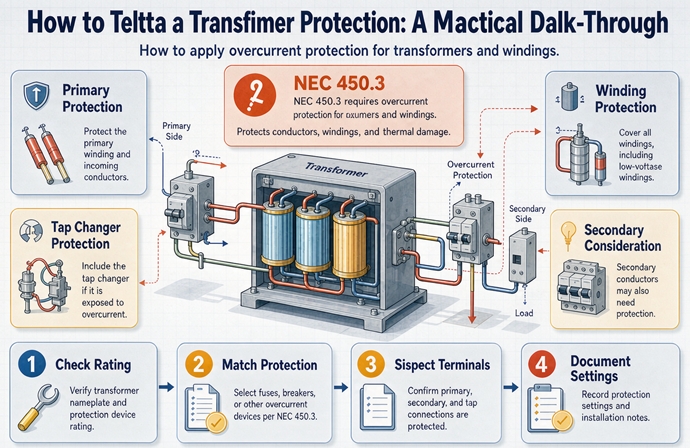
Article 450.3 caps the device, not the wire. At 1,000 volts or less, take 125 percent of primary full load current and round up to the next standard rating. Protect both sides and the primary ceiling rises to 250 percent, where you round down, while the secondary sits at 125 percent. Above 1,000 volts, impedance and supervision decide.
That paragraph is the whole section in five sentences, and it is also where most of the confusion starts, because two of those sentences sound like they contradict each other. They do not. They live in different columns of the same row, and the rounding runs in opposite directions.
This page walks the two tables the way you actually meet them: on a submittal, in a plan review comment, or standing in front of a transformer that somebody already ordered. Every percentage here comes from Table 450.3(A) and Table 450.3(B) as printed, including the notes, because the notes do most of the work and almost nobody quotes them.
What 450.3 actually protects
Three separate questions get answered by three different parts of the code, and they get tangled because one device often appears to answer all three.
Three jobs and only one of them is in this section
The first question is what protects the transformer winding. That is 450.3, and nothing else.
The second is what protects the primary conductors feeding it. That is Article 240, specifically 240.4, plus the feeder tap rules in 240.21(B) if the primary is tapped rather than run from a dedicated breaker.
The third is what protects the secondary conductors leaving it. That is 240.21(C), the transformer secondary tap rules, and for a four wire wye secondary the answer is almost never the primary device.
A 75 kVA unit with a 125 amp breaker on the primary is fully compliant with 450.3(B) on the primary only row. That same breaker protects nothing on the secondary side if the secondary is 208Y/120, because a four wire wye has a grounded conductor and the primary device cannot be counted on to open a secondary fault. The transformer is protected. The wire is not.
This is the single most common plan review comment on transformer installations, and it is not a trick. It is two calculations that look like one.
What the section leaves to other articles
Four things sit outside 450.3 and get assumed into it by mistake.
Interrupting rating is not in 450.3. A device can be correctly sized to 125 percent and still be unable to clear the fault current at that bus. That is 110.9 and 110.10, and it is a separate study.
The disconnecting means is not in 450.3. It is 450.14, and it has its own exceptions.
The grounding and bonding of the secondary is 250.30 if the transformer is a separately derived system, which a delta-wye unit almost always is.
The temperature and siting rules for dry types indoors are 450.21 and 450.23, and they decide whether you need a fire rated room, which is a construction cost, not an electrical one.
None of those four are optional because 450.3 was satisfied. A package that clears 450.3 and misses 450.14 fails inspection every time.
Which table you are in
The header of Table 450.3(A) says transformers over 1,000 volts. The header of Table 450.3(B) says 1,000 volts nominal or less. That is the entire instruction, and it is written about the transformer, not about the building.
The 1,000 volt line belongs to the transformer
A 4,160 volt to 480 volt unit uses Table 450.3(A), even though everything downstream is low voltage and even though the secondary device will be an ordinary 480 volt breaker. The transformer’s own voltage class is over 1,000 volts, so the high side table governs.
A 480 volt to 208Y/120 unit uses Table 450.3(B), even when it is fed from a 13.8 kV service through an upstream unit. The service voltage is irrelevant. The transformer sees 480 volts on its primary, so the low side table governs.
This trips people because the two tables look similar in shape and completely different in generosity. On a 1,000 kVA unit, Table 450.3(B) gives a primary ceiling of 1,600 amps and Table 450.3(A) at 13.8 kV gives a ceiling between 110 and 300 amps, depending on which row you land in. Applying the wrong table is not a small error. It is a factor of five.
The one case where the header is ambiguous
A step-up transformer with a 480 volt primary and a 4,160 volt secondary is the one place the header does not read cleanly, because the primary is under 1,000 volts and the secondary is not.
The safe reading is that the higher winding voltage governs, so the unit goes to Table 450.3(A). That is also the conservative reading, because Table 450.3(A) requires secondary protection at any location, which Table 450.3(B) does not.
If you have a step-up unit on a project, put the question in writing to the authority having jurisdiction before you order gear. It is a five minute email and it settles an argument that otherwise happens after the switchgear is built.
Table 450.3(B) column by column
This is the table that governs almost everything sold in North America at distribution voltage. Two rows, five percentage columns, and two notes that change the answer.
| Protection method | Primary, 9 A or more | Primary, less than 9 A | Primary, less than 2 A | Secondary, 9 A or more | Secondary, less than 9 A |
|---|---|---|---|---|---|
| Primary only | 125 percent, Note 1 | 167 percent | 300 percent | Not required | Not required |
| Primary and secondary | 250 percent, Note 3 | 250 percent, Note 3 | 250 percent, Note 3 | 125 percent, Note 1 | 167 percent |
Read the pattern before the numbers. The top row has no secondary device at all, so the primary device is the only thing standing between a winding and a fault, and the ceiling is tight. The bottom row adds a secondary device that handles overload, so the primary is allowed to be generous and the tight ceiling moves to the secondary.
The 125 percent column and the note that lets you round up
Primary only, current of 9 amps or more, ceiling is 125 percent of primary full load current. On a 480 volt three phase unit that is almost every size you will ever specify, because 9 amps corresponds to about 7.5 kVA.
The arithmetic, with the rounding that Note 1 permits:
| kVA at 480 V | Primary FLA | 125 percent | Next standard rating | Device as a multiple of FLA |
|---|---|---|---|---|
| 15 | 18.0 | 22.6 | 25 | 1.39 |
| 30 | 36.1 | 45.1 | 50 | 1.39 |
| 45 | 54.1 | 67.7 | 70 | 1.29 |
| 75 | 90.2 | 112.8 | 125 | 1.39 |
| 112.5 | 135.3 | 169.2 | 175 | 1.29 |
| 150 | 180.4 | 225.5 | 250 | 1.39 |
| 225 | 270.6 | 338.3 | 350 | 1.29 |
| 300 | 360.8 | 451.1 | 500 | 1.39 |
| 500 | 601.4 | 751.8 | 800 | 1.33 |
| 750 | 902.1 | 1,127.6 | 1,200 | 1.33 |
| 1,000 | 1,202.8 | 1,503.5 | 1,600 | 1.33 |
Look at the last column. The device you actually install is never 125 percent of full load current. It is between 129 and 139 percent, because the standard rating ladder is coarse and Note 1 lets you go up.
Note 1 reads: where 125 percent of this current does not correspond to a standard rating of a fuse or nonadjustable circuit breaker, a higher rating that does not exceed the next higher standard rating shall be permitted. Two words in there matter. Next higher, and does not exceed. You get one step, not a ladder.
So a 75 kVA unit at 480 volts gets a 125 amp device, not a 150. The calculation gives 112.8. The next standard rating is 125. You may use it. You may not use 150, because 150 is not the next higher standard rating, it is two steps up.
That distinction sounds academic until a reviewer catches a 150 amp breaker on a 75 kVA unit, which is 166 percent of full load current and outside the table.
The 9 ampere and 2 ampere rows nobody checks
The 167 percent and 300 percent rows exist because a small transformer cannot survive a device sized to 125 percent. At 1 kVA and 240 volts single phase, full load current is 4.17 amps, 125 percent is 5.2 amps, and the smallest common device is 15 amps. The device would nuisance trip on every energization. So the table gives the small unit room.
Where the thresholds land, which is the part nobody publishes:
| Primary | 9 A corresponds to | 2 A corresponds to |
|---|---|---|
| 480 V, three phase | 7.5 kVA | 1.7 kVA |
| 600 V, three phase | 9.4 kVA | 2.1 kVA |
| 480 V, single phase | 4.3 kVA | 1.0 kVA |
| 240 V, single phase | 2.2 kVA | 0.5 kVA |
So a 2 kVA control transformer at 480 volts single phase draws 4.17 amps, sits in the middle row, and gets 167 percent, which is 6.96 amps. Here is the sharp edge: Note 1 is attached to the 125 percent cells, not to the 167 percent cells. There is no next size up in that column. The largest standard rating that does not exceed 6.96 amps is 6 amps.
Most people install a 10 amp fuse. That is 240 percent of full load current, in a row whose ceiling is 167 percent. It works, it never trips, and it is outside the table.
The 250 percent column, where you round down
Add a secondary device and the primary ceiling jumps from 125 to 250 percent. This is the part everyone knows. What almost nobody writes down is the rounding direction, and it runs the other way.
The 250 percent cells cite Note 3, not Note 1. There is no next size up in that column. You take the largest standard rating that does not exceed the calculated value, which means you round down.
| kVA at 480 V | Primary FLA | 250 percent | Largest standard not exceeding | Realized multiple |
|---|---|---|---|---|
| 45 | 54.1 | 135.3 | 125 | 2.31 |
| 75 | 90.2 | 225.5 | 225 | 2.49 |
| 112.5 | 135.3 | 338.3 | 300 | 2.22 |
| 150 | 180.4 | 451.1 | 450 | 2.49 |
| 225 | 270.6 | 676.6 | 600 | 2.22 |
| 500 | 601.4 | 1,503.5 | 1,200 | 2.00 |
A 112.5 kVA unit has a 250 percent ceiling of 338.3 amps. The answer is 300 amps. Not 350. A 500 kVA unit has a ceiling of 1,503.5 amps. The answer is 1,200 amps, not 1,600. That last one gives away half a multiple: you were promised 2.5, you get 2.0.
Now put the two columns side by side for the same unit and see what the option is actually worth. A 45 kVA transformer at 480 volts:
- Primary only, 125 percent, rounded up: 70 amps, which is 1.29 times full load current.
- Both sides, 250 percent, rounded down: 125 amps, which is 2.31 times full load current.
The table appears to offer double. The rounding turns it into 1.8 times. That gap is the difference between a device that rides through inrush and one that does not, which is why the exact number matters and “about two and a half times” does not.
Note 3, the six times escape hatch
Note 3 is the most useful note in the table and the least used. A transformer equipped with coordinated thermal overload protection by the manufacturer, arranged to interrupt the primary current, may have primary protection set at up to six times rated current for impedance of 6 percent or less, and four times for impedance over 6 percent up to 10 percent.
On a 45 kVA unit that is 325 amps, so a 350 amp device. On a 75 kVA unit it is 541 amps, so a 600 amp device.
That is a very large number, and it is not a loophole. The manufacturer has built a thermal relay into the transformer that opens the primary on a real overload. The 350 amp breaker is there for short circuit only, so it can be sized for the fault and left alone by the inrush. If your small transformer nuisance trips and you have exhausted the 250 percent row, this is the legitimate path, and it comes from the transformer supplier, not from the breaker catalog.
Ask for it on the RFQ by name: coordinated thermal overload protection, arranged to interrupt the primary current. If the quote does not say that sentence, Note 3 does not apply to the unit you are buying.
Table 450.3(A) is where the money is
Above 1,000 volts the table grows from two rows to five, because two more variables appear: the location, and the transformer impedance. Those two variables are worth more money than the whole low voltage table.
| Location | Impedance | Primary breaker | Primary fuse | Secondary over 1,000 V, breaker | Secondary over 1,000 V, fuse | Secondary 1,000 V or less |
|---|---|---|---|---|---|---|
| Any location | 6 percent or less | 600 percent | 300 percent | 300 percent | 250 percent | 125 percent |
| Any location | Over 6, up to 10 percent | 400 percent | 300 percent | 250 percent | 225 percent | 125 percent |
| Supervised only | Any | 300 percent | 250 percent | Not required | Not required | Not required |
| Supervised only | 6 percent or less | 600 percent | 300 percent | 300 percent | 250 percent | 250 percent |
| Supervised only | Over 6, up to 10 percent | 400 percent | 300 percent | 250 percent | 225 percent | 250 percent |
At any location, the secondary device is not optional
Read the first two rows for the column that says Not required. There is none. Every cell has a number.
That is the structural fact of Table 450.3(A), and it is easy to miss because the low voltage table has Not required written twice in plain sight. Above 1,000 volts, at a location that is not supervised, you must protect the secondary. There is no primary only option at all.
For a 1,000 kVA unit with a 480 volt secondary, that means a 1,600 amp device on the low side: 1,202.8 amps of secondary full load current, 125 percent is 1,503.5, next standard rating 1,600. A 1,600 amp main, a 1,600 amp bus, and the switchgear that goes with it.
If the primary is 13.8 kV, the primary ceiling at 6 percent impedance is 251 amps, so a 300 amp breaker. A 300 amp breaker upstream and a 1,600 amp breaker downstream, for the same transformer. That asymmetry is the table working as intended, not a mistake.
Supervised, and what that definition is worth
The third row down is the one that changes the project budget. It says, for a supervised location at any impedance: primary breaker 300 percent, primary fuse 250 percent, secondary not required.
The definition is in Note 3 of Table 450.3(A): a supervised location is a location where conditions of maintenance and supervision ensure that only qualified persons monitor and service the transformer installation. It is about who has access and what they know, not about whether the room is locked.
A locked electrical room in an office building that the building engineer opens with a key is usually not supervised in this sense, because the building engineer is not a qualified person monitoring a 13.8 kV transformer. A utility substation, an industrial plant with a maintained electrical department, and a campus distribution room staffed by the electrical shop usually are.
What it is worth, on the same 1,000 kVA 13.8 kV unit:
| Case | Primary device | Low side device | Low side bus |
|---|---|---|---|
| Any location, 6 percent or less | 300 A breaker | 1,600 A at 125 percent | 1,600 A |
| Supervised, primary only | 150 A breaker at 300 percent | None required | None |
| Supervised, both sides | 300 A breaker | 3,000 A at 250 percent | Beyond standard |
The middle row removes a 1,600 amp breaker, a 1,600 amp section of switchboard, and the floor space for it. On a project that is real money, and it is available only if the room genuinely meets the definition and you are prepared to defend that in writing.
The bottom row is the odd one. In a supervised location that also protects the secondary, the low side ceiling is 250 percent instead of 125 percent, which on this unit is 3,007 amps. That is beyond any standard bus, so nobody builds it for a 1,000 kVA unit. It exists for larger units where 250 percent of a small secondary current is still a practical number.
The 6 percent cliff
Here is the fact that costs the most and appears in no guide I have read. The impedance bands in Table 450.3(A) are not more than 6 percent, and over 6 up to 10 percent. Common medium voltage distribution transformers are quoted at 5.75 percent, 6.0 percent, 6.5 percent, and 7.5 percent. Two of those land in the generous band and two do not.
| Unit | Impedance | Primary FLA at 13.8 kV | Ceiling at 600 percent | Ceiling at 400 percent |
|---|---|---|---|---|
| 1,000 kVA | 5.75 or 6.0 percent | 41.8 A | 251 A, use 300 A | not applicable |
| 1,000 kVA | 6.5 or 7.5 percent | 41.8 A | not applicable | 167 A, use 175 A |
| 1,500 kVA | 5.75 or 6.0 percent | 62.8 A | 377 A, use 400 A | not applicable |
| 1,500 kVA | 6.5 or 7.5 percent | 62.8 A | not applicable | 251 A, use 300 A |
Half a percentage point of impedance moves the primary ceiling by a third. On the 1,000 kVA unit it is the difference between a 300 amp breaker and a 175 amp breaker, and the 175 amp breaker has a much harder time riding through inrush on a 42 amp transformer.
That creates a real conflict, because the reason you would specify 6.5 percent instead of 5.75 is to reduce the fault current downstream, and one of the ways the code lets you control fault current is a bigger primary device. If your fault study says the switchgear needs lower available current, the impedance bump that fixes it also takes away a third of your protection ceiling. Both effects have to be looked at together, and they almost never are, because the impedance is chosen by the transformer supplier and the breaker by the electrical engineer.
Order the impedance in writing, confirm which band it falls in, and size the primary device against that band. A submittal that says 6.5 percent impedance next to a breaker sized at 600 percent is a rejection waiting to happen.
Breaker against fuse is a factor of two
Look across the first row of Table 450.3(A). Primary breaker, 600 percent. Primary fuse, 300 percent. Same transformer, same impedance, same location, and the device type alone doubles your ceiling.
For the 1,000 kVA unit at 13.8 kV that is 300 amps with a breaker and 150 amps with a fuse. Both are legal. Neither is better in general.
The breaker is resettable, has adjustable settings, and can be coordinated with downstream devices. The fuse is faster, has a higher interrupting rating for the money, and needs no settings to be wrong. On a 13.8 kV transformer that feeds a process where a trip means a shift lost, the breaker usually wins. On a unit where the fault current is high and the switchgear budget is thin, the fuse does the same job for less.
The point is that this is a decision, and it is made on the one line before the gear is ordered. Choosing “breaker, we always use breakers” quietly gives up half the allowance the table offers, and then someone spends a week trying to make an inrush trip go away.
The walk-through, in order
Here is the sequence, and it is the same seven steps for both tables.
Seven steps
- Confirm the transformer voltage class. Over 1,000 volts goes to Table 450.3(A). 1,000 volts or less goes to Table 450.3(B). Use the transformer’s rating, not the service.
- Get the nameplate values. kVA, primary voltage, secondary voltage, phases, and percent impedance. Impedance is on the nameplate and on the test report, and it is the value that decides the row in Table 450.3(A).
- Compute full load current on both sides. Three phase is kVA times 1,000 divided by 1.732 times volts. Single phase is kVA times 1,000 divided by volts. Do both sides even if you only need one, because you will need the other for the conductor check.
- Decide the protection method. Primary only, or primary and secondary. This is a design decision, not a table lookup. Primary only is cheaper and protects the transformer adequately. Primary and secondary protects the secondary conductors, gives the primary a higher ceiling, and costs a device.
- Pick the row. For Table 450.3(B), that means which current band the primary falls in. For Table 450.3(A), that means the location and the impedance band.
- Apply the percentage, then round in the correct direction. Round up if the cell cites Note 1. Round down if it does not.
- Check what the device rating drags behind it. Primary conductor ampacity, secondary conductor protection, bus rating, interrupting rating, and the disconnect. Steps one through six protect the transformer. Step seven protects the installation.
The step people skip is six, and the step people do last and regret is seven.
A sheet that fits on one page
| Line | What goes there |
|---|---|
| Transformer | kVA, primary volts, secondary volts, phases, impedance, winding material |
| Table | 450.3(A) or 450.3(B), and why |
| Primary FLA | calculation shown |
| Secondary FLA | calculation shown |
| Protection method | primary only, or primary and secondary |
| Primary device | percentage, calculated value, standard rating selected, rounded up or down and the note that allows it |
| Secondary device | same four items, or “not required per row” |
| Primary conductors | ampacity and size, with the 240.4 basis |
| Secondary conductors | tap rule applied and length |
| Bus rating | panelboard or switchboard main bus |
| Interrupting rating | available fault current, device rating, margin |
| Disconnect | 450.14 method and location |
Twelve lines. If a submittal has all twelve, it will pass review on the first pass in most jurisdictions, and the reviewer can check it in four minutes. That is the actual purpose of the sheet.
Five worked examples
45 kVA, primary only
480 volts to 208Y/120, three phase, dry type. Primary full load current is 45,000 divided by 1.732 times 480, which is 54.1 amps. That is more than 9 amps, so the top row applies: 125 percent, which is 67.7 amps.
67.7 is not a standard rating. Note 1 applies. The next higher standard rating is 70 amps. A 70 amp device is the answer, and it is 1.29 times full load current.
Now the consequence. The secondary is a four wire wye at 208Y/120. Primary only protection does not protect those secondary conductors, because 240.21(C)(1) does not extend to a four wire wye. The secondary conductors need protection under another 240.21(C) provision, usually the 25 foot rule, or a secondary main. Budget for it before you decide that primary only saved you a breaker.
150 kVA, both sides
480 volts to 208Y/120, three phase. Primary full load current is 180.4 amps, secondary is 416.4 amps.
Primary ceiling at 250 percent is 451.1 amps. The 250 percent cell cites Note 3, not Note 1, so there is no next size up. The largest standard rating not exceeding 451.1 is 450 amps. A 450 amp device, which is 2.49 times full load current.
Secondary ceiling at 125 percent is 520.4 amps. This cell cites Note 1, so you may go up one step to 600 amps.
Two devices, 450 on the primary and 600 on the secondary, for a transformer whose own full load currents are 180 and 416. Every number is larger than the transformer’s rating, and that is normal. The devices are protecting a winding with thermal mass, not a conductor with a 75 degree limit.
1,000 kVA at 13.8 kV, any location
Primary 13,800 volts, secondary 480 volts, three phase, 5.75 percent impedance, installed in a building electrical room that is not supervised.
Primary full load current is 41.84 amps. The impedance is not more than 6 percent, and the location is any location, so the top row applies: primary breaker 600 percent, primary fuse 300 percent. With a breaker that is 251 amps, and 300 amps is the next standard rating above it. Note 1 of Table 450.3(A) permits a higher rating, and above 1,000 volts the language is the next higher commercially available rating rather than the next standard rating. In practice 300 amps is a standard breaker frame, so 300 amps.
Secondary full load current is 1,202.8 amps. At any location the low side device is required, at 125 percent, which is 1,503.5 amps, next standard rating 1,600 amps.
So the package is a 300 amp breaker on the 13.8 kV side and a 1,600 amp breaker on the 480 volt side. The primary device is a quarter of the secondary device, and both are correct.
One more check on that number. With a fuse, 300 percent gives 125.5 amps. Note 1 of Table 450.3(A) permits the next higher commercially available rating, not the next higher standard rating, and the two lists are not the same above 1,000 volts. A 110 amp medium voltage fuse is not a stocked item in most lines while 125 amp is, so the practical ceiling lands at 125 amps rather than 150. Confirm against the fuse catalog you are actually specifying, because this is one place the wording of the note changes the answer.
The same unit in a supervised room
Same transformer, same impedance, but in a room that genuinely meets the Note 3 definition.
Now the primary only row is available: 300 percent with a breaker, which is 125.5 amps, next standard 150 amps. And the secondary device is not required at all.
Compare the two answers honestly. Any location: 300 amp primary breaker plus a 1,600 amp secondary breaker with a 1,600 amp bus. Supervised: a 150 amp primary breaker and nothing on the secondary.
That is the same transformer, the same fault current, and a different switchgear package worth a serious amount of money. It is also the reason the supervised definition gets argued about on every medium voltage job, and why it belongs in writing with the client’s maintenance organization named, not assumed.
A 2 kVA control transformer
480 volts to 120 volts, single phase, dry type, feeding a control panel.
Primary full load current is 4.17 amps. That is less than 9 amps and more than 2, so the middle row applies: 167 percent, which is 6.96 amps.
No note attaches to that cell, so no round up. The largest standard rating not exceeding 6.96 amps is 6 amps. A 6 amp fuse, or a 6 amp breaker if you can find one in that frame.
This is the case where field practice and the table part company most often, because 10 amp fuses are in every van and 6 amp fuses are not. A 10 amp device is 240 percent of full load current on a transformer that the table caps at 167. It will never nuisance trip, which is exactly why it stays installed, and it is not compliant.
If the panel really needs a 10 amp device, the path is Note 3: order the transformer with coordinated thermal overload protection, and the ceiling moves to 6 times rated current for a unit at 6 percent impedance or less.
What the device rating drags behind it
Step seven is where the money and the rework live, and it has five parts.
Primary conductors
The device rating sets the conductor, not the other way around. A 125 amp device needs a conductor with at least 125 amps of ampacity, unless 240.4(B) lets you use the next size up because the ampacity does not match a standard rating.
That is a small allowance and it is capped at 800 amps. Above 800 amps, 240.4(C) removes it: the conductor ampacity must be equal to or greater than the device rating, with no next size up.
So the protection choice in step four changes the wire in step seven. On a 75 kVA unit:
| Choice | Primary device | Smallest 75 C copper |
|---|---|---|
| Primary only, 125 percent | 125 A | 1 AWG |
| Both sides, 250 percent | 225 A | 4/0 |
Going from a 125 amp device to a 225 amp device moves the primary conductor from 1 AWG to 4/0. That is not a rounding difference, it is a different wire pull, a different lug, and a different conduit. On a 500 kVA unit the 250 percent route needs a 1,200 amp device, which is past the single conductor range and into parallel sets.
This is the trade nobody puts on the same line: the 250 percent row buys inrush headroom and pays for it in primary copper. On a short primary run it is cheap. On a 200 foot run from a remote switchboard it is not.
Secondary conductors and 240.21(C)
The transformer secondary tap rules are 240.21(C), and they are where primary only protection gets rescued or does not.
240.21(C)(1) is the provision that lets the primary device protect the secondary conductors, and it has a shape requirement. It works for a two wire secondary, and for a three wire delta, and it does not work for a four wire wye. Most commercial secondaries in North America are four wire wye, which means (C)(1) is unavailable on the majority of the units you will specify.
What remains is the 10 foot rule, the 25 foot rule, the outside rule, and the industrial unlimited length rule, each with its own conditions on conductor ampacity, physical protection, and where the overcurrent device sits.
The practical consequence is simple. A primary only design on a 208Y/120 secondary is not a primary only design at all. It is a design with a secondary tap rule attached, and that tap rule has a length limit printed in it.
The panelboard bus
The secondary device rating sets the bus. 125 percent of secondary full load current is always more than the transformer’s own rating, so the panelboard is always bigger than the transformer suggests.
| kVA | Secondary FLA at 480 V | 125 percent | Bus rating |
|---|---|---|---|
| 500 | 601.4 A | 751.8 A | 800 A |
| 750 | 902.1 A | 1,127.6 A | 1,200 A |
| 1,000 | 1,202.8 A | 1,503.5 A | 1,600 A |
| 1,500 | 1,804.2 A | 2,255.3 A | 2,500 A |
A 1,000 kVA transformer feeding a 480 volt switchboard needs a 1,600 amp bus, because the device in front of it is 1,600 amps. Buyers who compare the transformer kVA to the switchboard rating and conclude the switchboard is oversized are reading the wrong number. The switchboard is sized to the device, and the device is sized to 125 percent of the transformer.
This is also where the supervised allowance at Table 450.3(A) shows up as a real saving, and where the 250 percent secondary allowance becomes impractical, because 250 percent of 1,202.8 is 3,007 amps and nobody builds that bus for a 1,000 kVA unit.
Interrupting rating
450.3 is silent on interrupting rating, and that silence is not permission.
A device can be perfectly sized to 125 percent and still be unable to clear a fault. A 1,000 kVA unit at 5.75 percent impedance on a 480 volt bus produces about 20.9 kA of available fault current. A 10 kA rated device on that bus is correctly sized and unsafe.
Available fault current comes from the transformer impedance and the source, and the device rating has to exceed it with margin. That is 110.9 and 110.10 work, and it is a different calculation from 450.3 with a different input. Do both, and put both on the sheet.
The disconnect
450.14 requires a disconnecting means for each transformer, with exceptions that include dry type units at 1,000 volts or less installed in the open on walls or columns, and units not over 50 kVA in certain hollow spaces.
The mistake is treating the 450.3 device as the disconnect. A maximum rated overcurrent device is not a disconnecting means unless it is also listed and marked as one and meets the requirements of 450.14. On a 1,600 amp secondary main that is a lockable breaker. On a 300 amp medium voltage primary it is a load break switch, and the breaker upstream of it may be in another room.
The two requirements are separate. Satisfying one does not satisfy the other.
The question people actually ask
The reverse question comes up on every retrofit: I have a 400 amp breaker and a spare feeder, what is the biggest transformer I can put on it.
Work backwards through the 125 percent row. The device may not exceed 125 percent of primary full load current, with one step up under Note 1. So primary full load current may not exceed 400 divided by 1.25, which is 320 amps.
At 480 volts three phase, 320 amps is 266 kVA of transformer. The largest standard rating under that is 225 kVA.
| Existing device, 480 V primary only | Largest standard transformer |
|---|---|
| 100 A | 45 kVA |
| 150 A | 75 kVA |
| 200 A | 112.5 kVA |
| 250 A | 150 kVA |
| 300 A | 150 kVA |
| 350 A | 225 kVA |
| 400 A | 225 kVA |
| 500 A | 300 kVA |
| 600 A | 300 kVA |
| 800 A | 500 kVA |
Two things to notice. First, 300 and 250 amps both land on 150 kVA, because the standard kVA ladder is coarse. Second, a 400 amp breaker buys nothing over a 350 amp breaker. The ladder skips, and the skip wastes capacity.
This table is also the fastest way to answer the question that opens most conversations about a spare breaker: the answer is usually one size smaller than the person hoped, and the arithmetic takes thirty seconds.
Six numbers that get written wrong
| What gets written | What the table says | Why it happens |
|---|---|---|
| 125 percent is the target | 125 percent is a ceiling, and Note 1 makes the installed device 129 to 139 percent | The word maximum gets read as recommended |
| 250 percent rounds up like 125 percent | The 250 percent cells have no note, so you round down | Two adjacent columns, two directions |
| 167 percent also rounds up | No note in that cell, so a 6.96 amp ceiling means a 6 amp device | The round up habit carries across columns |
| 480 volt transformer in a 13.8 kV building uses the low table | The transformer’s own voltage decides, so a 4,160 volt primary uses Table 450.3(A) | Building voltage gets confused with transformer voltage |
| 6.5 percent impedance is close enough to 6 | The band is not more than 6, so 6.5 drops the breaker ceiling from 600 to 400 percent | The band boundary reads as approximate |
| The 450.3 device is the disconnect | 450.14 is a separate requirement with its own exceptions | One device appears to do both jobs |
What belongs on the submittal
Reviewers reject transformer packages for a short list of reasons, and every one of them is a missing number rather than a wrong design.
The table above is the checklist. Beyond it, four documents make the package close cleanly on the first pass.
The nameplate or the factory test report, showing impedance. Not the catalog page, which lists a range. The impedance band decides the row in Table 450.3(A), and a range cannot be checked against a boundary.
The fault current calculation at the secondary bus, with the device interrupting rating beside it. This is the one a reviewer will ask for and the one that is most often missing.
The 240.21(C) basis for the secondary conductors, named by subparagraph, with the conductor length. Writing “per 240.21(C)” without the length and the subparagraph tells the reviewer nothing.
The 450.14 disconnect location, on the one line, with the room. A disconnect that exists but is not shown is a field argument.
If you are buying the transformer and the gear together, all four come from the same package and the review is a formality. If they come from three suppliers, the impedance band, the bus rating, and the interrupting rating are the three places the packages will disagree, and the disagreement surfaces after delivery.
FAQ
What is the difference between Table 450.3(A) and Table 450.3(B)?
The transformer voltage decides. Table 450.3(A) governs transformers over 1,000 volts, so a 4,160 volt to 480 volt unit uses it even though the secondary is low voltage. Table 450.3(B) governs 1,000 volts or less, so a 480 volt to 208Y/120 unit uses it even when it is fed from a 13.8 kV service. The building voltage is irrelevant, and mixing the two tables is a factor of five error.
Why does 450.3(B) allow 250 percent on the primary when both sides are protected?
Because the secondary device handles overload, so the primary only has to survive inrush and clear a fault. Inrush on a dry type unit runs eight to twelve times full load current for a fraction of a cycle, and a device capped at 125 percent will not hold it. The 250 percent ceiling buys that headroom. The trade is a secondary device and larger primary conductors.
Does 250 percent round up to the next standard breaker size?
No, and this is the most common error on the table. The 250 percent cells cite Note 3, not Note 1, and Note 1 is the only provision that permits rounding up. A 112.5 kVA unit at 480 volts has a 250 percent ceiling of 338.3 amps, so the answer is 300 amps, not 350. A 500 kVA unit has a ceiling of 1,503.5 amps, so the answer is 1,200 amps, and the realized multiple drops from 2.5 to 2.0.
What does a supervised location mean in Table 450.3(A)?
Note 3 defines it as a location where conditions of maintenance and supervision ensure that only qualified persons monitor and service the transformer installation. It is about who has access and what they are qualified to do, not whether the room is locked. A room a building engineer opens with a key usually does not qualify for a medium voltage unit. Getting it right removes a secondary device on a 1,000 kVA unit.
Why does 6.5 percent impedance change the answer?
Because Table 450.3(A) has two impedance bands, not more than 6 percent and over 6 up to 10 percent, and the primary breaker ceiling drops from 600 to 400 percent between them. On a 1,000 kVA unit at 13.8 kV that is a 300 amp breaker against a 175 amp breaker, a third less headroom for inrush on a 42 amp transformer. Common 5.75 and 6.0 percent units sit in the generous band; 6.5 and 7.5 percent do not.
Is a fuse better than a breaker for transformer primary protection?
Neither is better in general, but above 1,000 volts the choice changes the ceiling by a factor of two. Table 450.3(A) allows a primary breaker at 600 percent and a primary fuse at 300 percent on a unit at 6 percent impedance or less. A breaker is resettable, adjustable, and coordinates downstream. A fuse is faster, cheaper, and has no settings to get wrong. Decide on the one line.
Does 450.3 protect the secondary conductors?
No. 450.3 protects the transformer winding. Secondary conductors are protected under 240.21(C), and the provision that lets the primary device protect them, 240.21(C)(1), does not apply to a four wire wye secondary. Since most commercial secondaries are four wire wye, a primary only design on a 208Y/120 unit needs a secondary tap rule with a length limit or a secondary main.
Why is the panelboard bigger than the transformer?
Because the secondary device is 125 percent of secondary full load current, and the bus is sized to the device. A 1,000 kVA unit at 480 volts has 1,202.8 amps of secondary current, the device is 1,600 amps, and the bus has to match. The transformer is 1,000 kVA and the switchboard is 1,600 amps. Both are correct, and the switchboard is not oversized.
What is the 167 percent row for?
Small transformers whose full load current is so low that a device at 125 percent would trip on inrush. The row applies to primary currents under 9 amps, which is about 7.5 kVA on a 480 volt three phase unit and about 2.2 kVA on a 240 volt single phase unit. Note 1 does not attach to that cell, so there is no rounding up, and a 6.96 amp ceiling means a 6 amp device.
Can I use a bigger breaker if the transformer has thermal overload protection?
Yes, under Note 3 to Table 450.3(B), if the manufacturer provides coordinated thermal overload protection arranged to interrupt the primary current. The primary device may then be set at up to six times rated current for impedance of 6 percent or less, or four times for impedance over 6 up to 10 percent. On a 45 kVA unit that is 325 amps, so a 350 amp device. The sentence has to appear on the quote.
Does 450.3 require a disconnect at the transformer?
No. 450.14 does, with its own exceptions for dry type units at 1,000 volts or less installed in the open and for small units in certain hollow spaces. A device sized to 450.3 is not a disconnecting means unless it is listed and marked as one and meets 450.14. On a medium voltage primary the disconnect is often a load break switch in a different room from the breaker.
What is the largest transformer a 400 amp breaker can protect?
At 480 volts with primary only protection, primary full load current may not exceed 400 divided by 1.25, which is 320 amps. That is 266 kVA of transformer, and the largest standard rating under it is 225 kVA. A 350 amp breaker also lands on 225 kVA, so the 400 amp frame buys nothing over the 350, because the standard kVA ladder is coarser than the breaker ladder.
Free: Transformer Specification Checklist
The exact RFQ sheet our engineers use — send it and get a quoted proposal within 24h.
Download checklist