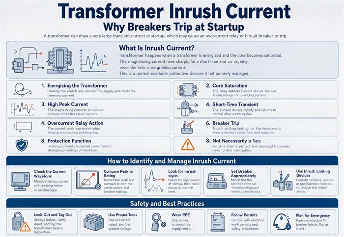
A 1000 kVA transformer at 480 V draws 1,203 A running and roughly 10,800 A on the first half cycle. Nothing is broken. Every protection layer upstream sees a fault, and the instantaneous element is the one that acts. Here is where that number comes from, how long it lasts, and how to spec around it.
What the breaker sees
Five devices sit between the utility and your transformer, and inrush looks different to each one. That difference is why the same energization can blow a fuse on one site and trip a relay on another with identical equipment.
| Device | What it actually responds to | What inrush looks like to it | What it does |
| Primary fuse | Heat, meaning I²t | 8 to 12 times full load for about 0.1 s | Opens if undersized, rides through if time delay |
| MCCB thermal element | Sustained overload | Too brief to register | Nothing |
| MCCB magnetic element | Instantaneous current over pickup | A bolted fault on one side only | Trips in 10 to 30 ms |
| Feeder relay, instantaneous (50) | Current over pickup, no intentional delay | A fault | Trips in 1 to 3 cycles |
| Differential relay (87T) | Current in minus current out | An internal fault | Blocks on second harmonic, if configured right |
The thermal element never operates. The event is over before it can heat anything. Every nuisance trip on a transformer energization is either a magnetic element, an instantaneous overcurrent element, a fuse, or a differential element that was not given the information it needed to know better.
That last point is the whole article in one sentence. Inrush is not a fault, but it is a fault-shaped signal, and protection only knows shapes.
The whole event fits in half a cycle
The flux budget
Close a breaker onto an unloaded transformer at the instant the voltage crosses zero, which is the worst case and roughly one attempt in six, and the core is asked for a specific quantity of flux.
The voltage integral from that instant is Φ(t) = Φn (1 − cos ωt). At half a cycle, cos ωt = −1, so the flux demand is 2 Φn. On top of that sits whatever residual flux the last de-energization left behind. Grain-oriented silicon steel commonly retains 0.6 to 0.8 of its saturation flux density, which on a core designed for 1.6 T peak is another 1.2 to 1.6 T, or 75 to 100 percent of the working flux.
| Closing angle | Residual flux | Peak flux demand | Against a 1.6 T design |
| Zero crossing | None | 2.0 Φn | 3.2 T |
| Zero crossing | 0.4 Φn | 2.4 Φn | 3.8 T |
| Zero crossing | 0.8 Φn | 2.8 Φn | 4.5 T |
| Voltage peak | Any | 1.0 Φn + Φr | 1.6 to 3.2 T |
A core with a saturation density of 2.0 T cannot hold 4.5 T. It is not slightly over the knee, it is more than twice past it. Above saturation the core stops behaving like iron and starts behaving like air, and the magnetizing branch collapses to the air-core inductance of the winding, which is smaller by a factor of hundreds.
That collapse is the current. It is not a slow build. The current peak lands at roughly 8.3 ms after a zero-crossing close, half a cycle in. Which is precisely inside the operating window of a magnetic trip or an instantaneous element, and far too fast for anything thermal to care.
What decides how big it gets
Four things, and only one of them is under the buyer’s control at the specification stage.
Closing angle. Random on a mechanically closed breaker, repeatable on a controlled one. This is the single largest variable, which is why the same unit energizes cleanly a hundred times and trips the hundred and first.
Residual flux. Set by what the core was doing when the breaker opened. A unit tripped off during a fault, or one that just came off a DC resistance test, carries much more of it than a unit that was switched off at light load.
Core steel and construction. Saturation density, permeability, and whether the unit is three-limb, five-limb, or wound core. A three-limb core forces zero-sequence flux through the tank and air, which makes the middle phase behave differently from the outer two, and the difference is large enough to matter on a Yg-delta unit.
Source impedance. Soft sources limit the peak but stretch the duration, and that trade is the subject of a later section because it is where most of the money gets lost.
The 12.5× coincidence behind most nuisance trips
Here is the arithmetic that nobody writes down, and it explains an entire class of site problem.
A molded case breaker feeding a transformer gets sized at 125 percent of primary full load current. That is the standard practice, it comes from the overload protection rules in NEC Article 450.3, and it has nothing to do with inrush.
A thermal-magnetic MCCB has a fixed magnetic trip, and the common factory setting is 10 times the breaker’s own rating.
Multiply the two:
1.25 × 10 = 12.5 × full load current
Now look at the inrush range for a distribution transformer: 8 to 12 times full load. The upper end of the inrush band is 12. The trip point is 12.5. The margin is four percent.
That is not a design. That is a coincidence that happens to work.
Why it works ninety-nine times
It works because 12× is the top of a distribution, because most energizations do not land on the worst closing angle with the worst residual flux aligned in the wrong direction, and because the reachable inrush peak on a given day is usually closer to 8 or 9.
Then the magnetic trip tolerance takes its cut. The instantaneous characteristic on a molded case breaker sits in a band of roughly plus or minus 20 percent. A nominal 12.5× can operate at 10×. On a day when the closing angle and the residual flux line up, the peak goes to 11 or 12, and a breaker that has been fine for six years opens on the first try after a utility outage.
Nothing failed. The band was always this thin. The site just finally landed inside it.
| Transformer | Primary FLA at 480 V | 125% breaker | Magnetic trip at 10× | Inrush at 9× | Margin |
| 500 kVA | 601 A | 800 A frame | 8,000 A | 5,412 A | 1.48 |
| 750 kVA | 902 A | 1,200 A frame | 12,000 A | 8,118 A | 1.48 |
| 1000 kVA | 1,203 A | 1,600 A frame | 16,000 A | 10,827 A | 1.48 |
| 1500 kVA | 1,804 A | 2,500 A frame | 25,000 A | 16,236 A | 1.54 |
The margin looks comfortable in that table because the breaker frame rounds up to the next standard size, and that rounding buys the headroom the 125 percent rule would otherwise have spent. Where the load sits close to a frame size and the rounding is small, the margin collapses toward 1.04, and the coincidence stops being generous.
The four settings that actually help
Raise the instantaneous pickup above the worst-case inrush. It works, and it is free if the breaker is adjustable. It also moves the device’s protection of the transformer in the wrong direction, so the new setting has to be checked against the minimum fault current at the end of the run, the conductor damage curve, and the arc flash calculation.
Add a short definite-time delay, 0.05 to 0.1 s. This is the cleanest fix on a relay, because inrush is over inside 0.5 s and a real fault is not. Check the coordination with downstream devices and the arc flash energy at the same time, and re-run the study rather than assuming.
Use a fuse with the right characteristic. The classic coordination rule for transformer primary fuses is that they must carry 12 times rated current for 0.1 s without opening. A fast-acting fuse picked close to full load will not, and someone climbs the pole.
Turn on second harmonic restraint in the differential relay. Inrush is rich in second harmonic, typically well above 15 percent of fundamental during the event, while an internal fault produces almost none. If the relay has the function and it is disabled, the relay will treat every energization as a fault.
That last one deserves a warning. Harmonic blocking solves energization, and it can also mask a genuine fault that happens to produce second harmonic through CT saturation. Blocking and restraint are different functions with different consequences. Know which one your relay is doing.
Where inrush stops being separable from a fault
Every setting fix above assumes there is daylight between the inrush peak and the fault current. On a lot of transformers there is. On some there is none.
One multiplication
Work in per unit on the transformer’s own base. Inrush is m times rated current, where m is 8 to 12. A bolted fault on the secondary is 1/Z times rated current, where Z is the transformer impedance in per unit.
The ratio of the two is:
inrush / fault = m × Z
| Impedance | 8× inrush | 10× inrush | 12× inrush |
| 2.0% | 0.16 | 0.20 | 0.24 |
| 4.0% | 0.32 | 0.40 | 0.48 |
| 5.75% | 0.46 | 0.58 | 0.69 |
| 8.0% | 0.64 | 0.80 | 0.96 |
| 10.0% | 0.80 | 1.00 | 1.20 |
| 12.0% | 0.96 | 1.20 | 1.44 |
| 14.0% | 1.12 | 1.40 | 1.68 |
The crossover, where inrush equals the bolted fault current, sits at Z = 1/m. That is 12.5 percent for 8× inrush, 10.0 percent for 10×, and 8.3 percent for 12×.
Distribution transformers live at 2 to 6 percent, so inrush is a third to two thirds of the fault current and a setting window exists, thin but real. Large power transformers live at 10 to 14 percent. At 12 percent impedance and 10× inrush, the ratio in the table is 1.20, which means the energization peak is larger than a bolted fault on the secondary.
One honest caveat, and it makes the problem worse rather than better: this table ignores source impedance. Add the utility or generator impedance and the fault current drops while the inrush does not, so the real ratio is higher than the table shows. Treat the table as the optimistic case.
What to do on the wrong side of the line
When the ratio is above about 0.8, an instantaneous element has no setting that both rides through energization and clears a fault at the transformer terminals. You have three options, and only one of them is a setting.
Accept a time delay and rely on the differential for fast clearing. A differential element with harmonic restraint does not care about the ratio, because it compares currents rather than magnitudes. The transformer is protected in one to two cycles by the 87T, and the backup overcurrent element is allowed to be slow.
Use a breaker with controlled closing. Point-on-wave switching closes the poles at a chosen instant rather than a random one, and the peak can be held near rated current. It is the only measure that removes the event rather than riding through it.
Split the transformer. Two smaller units in parallel have lower individual inrush and higher combined impedance, but you have doubled the energization events and added sympathetic inrush, which is its own problem and gets a section below.
How long it lasts
The published answer is “a few cycles to about a second,” which is accurate and useless for deciding whether a 0.1 s delay is enough.
The time constant that predicts it
The inrush current has a decaying DC component riding on an AC component, and the DC part decays with the winding’s own time constant:
τ = (X/R) / ω
At 60 Hz, ω is 377. Everything else is set by X/R, and X/R is set almost entirely by size.
| X/R | τ | Time to 5τ | In cycles at 60 Hz | Typical unit |
| 3 | 8.0 ms | 40 ms | 2.4 | Small dry type, control transformer |
| 5 | 13.3 ms | 66 ms | 4.0 | Distribution dry type |
| 10 | 26.5 ms | 133 ms | 8.0 | Small oil-immersed |
| 20 | 53.1 ms | 265 ms | 15.9 | Medium distribution |
| 40 | 106 ms | 531 ms | 31.8 | Large oil-immersed |
| 60 | 159 ms | 796 ms | 47.7 | Power transformer, GSU |
The range is more than an order of magnitude, and it is one parameter. A 0.1 s delay clears the small dry type comfortably and does nothing for the large unit, which is still at 60 percent of peak when the delay expires.
This is where the specification usually fails, because X/R is not printed on the nameplate. It is a design output, and if nobody asked for it, nobody has it.
How to measure it, if you have to
Most of the time you can settle an inrush argument with arithmetic and a relay settings file. When you cannot, because the settings are right and it still trips, you need the actual envelope.
Three channels, recorded simultaneously, at a sample rate of at least 5 kHz:
| Channel | Where to put it | What it tells you |
| Phase current, energizing side | CT or flexible probe, one phase minimum | The peak, and the DC offset direction |
| Phase voltage, same side | Voltage probe on the bushing or the breaker terminal | The closing angle, recoverable from the first sample |
| Neutral or residual current | Core balance CT if fitted | Whether the current is balanced or single-phase |
The closing angle matters more than the peak, because it is the one variable that can be changed at no cost. Record voltage on the same time base as current and read the phase angle at the first sample after the contacts part. A close at zero crossing with residual flux aligned against the incoming flux is the case that produces the number that tripped you. A close near voltage peak in the same installation produces something close to rated current, and proving that on a recorder ends the argument about whether the transformer is faulty.
Two practical traps. A split-core probe on a 3 kA peak will saturate and read low, so check the probe rating against the peak you expect rather than the running current. And record the full event for at least 2 s, because a recorder set to 0.1 s captures the peak and misses the duration, which is the half of the signature that decides whether a time delay will work.
Generator and inverter sources: a different number and a different duration
Everything above assumes a stiff utility source. Put the same transformer behind a generator and the physics does not change, but the numbers do, and they change in a direction that catches people out.
Two numbers, one transformer
A 1,000 kVA transformer energized from a utility draws an 8 to 12× peak for a few tens of milliseconds. The same transformer energized from an alternator draws something in the order of 0.75 to 1.25 times its own rated kVA, and takes one to two seconds to settle.
| Source | Peak | Duration | What limits it | What trips |
| Utility, stiff | 8 to 12× FLA | 0.05 to 0.5 s | Winding impedance, air-core inductance | Instantaneous element, fuse |
| Generator, comparable size | 0.75 to 1.25× kVA | 1 to 2 s | Alternator subtransient reactance | Generator breaker, AVR, undervoltage |
| Inverter, current limited | At the limit, flat | Until the inverter gives up | Inverter current limit | Inverter overload, DC bus |
The I²t comparison is instructive: 9× for 0.1 s is 8.1 per unit seconds, while 1.25× for 2 s is 3.1. The generator case carries less than half the heating energy and is far harder on the system, because the generator’s excitation system is trying to hold voltage while a reactive load it did not expect is holding it down.
Now the expensive consequence. Take the 8 to 12× figure, apply it to generator sizing, and you buy roughly ten times the alternator you need. The rule that matches test data is to size the generator at about 1.25 times the transformer kVA, with a permanent magnet or auxiliary winding excitation system rather than shunt excitation, and rate it at class F. At that ratio the transformer inrush pulls the generator to roughly 15 to 20 percent voltage dip, which is the number NFPA 110 works around for load acceptance.
| Transformer | 4.16 kV FLA | Generator at 1.25× | Voltage dip at 1.0 pu kVA ratio, X”d 0.15 to 0.20 |
| 500 kVA | 69 A | 625 kVA | 15 to 20% |
| 1000 kVA | 139 A | 1,250 kVA | 15 to 20% |
| 2000 kVA | 278 A | 2,500 kVA | 15 to 20% |
There is a trick that costs nothing and almost nobody uses: start the generator with excitation off, close the transformer breaker, then bring the excitation up. The voltage builds slowly, the core magnetizes gently, and the inrush event never happens. It requires an excitation system that can supply sustained current during the build, which is why it is specified rather than improvised. On an islanded site with a transformer bigger than half the generator, this is often the difference between a working scheme and a generator that will not pick up load.
The voltage dip that takes out everything else
Inrush is mostly reactive, so it does not stall an engine. It does depress voltage for one to two seconds on a generator, and one to two seconds is long enough to matter.
Variable frequency drives on the same bus see a DC bus undervoltage and trip on ride-through. Contactors drop out below about 70 percent voltage and do not reclose. PLC power supplies reset. Electronic ballasts restrike. A UPS may transfer to battery for a disturbance it did not need to see.
The sequence after that is familiar: the drives trip, the process stops, and the investigation starts with the drives instead of with the energization that caused it. If a site has a habit of “random drive trips whenever the backup generator runs,” this is the first place to look.
Sympathetic inrush: the running unit trips
Two transformers in parallel, one running loaded, one being energized. The breaker that opens is frequently the one on the unit that was already running and had been fine for years.
The mechanism is a voltage dip that is long relative to the flux. When the incoming transformer draws its inrush, bus voltage sags. The flux in the running transformer is the integral of that sagging voltage, so it drifts off center, and the running unit starts drawing a DC-biased current of its own. That current decays through the shared winding resistance with a time constant of seconds rather than cycles, because the only resistance in its path is copper.
The magnitude is not trivial. Published field and simulation work puts the sympathetic component at a substantial fraction of the energizing unit’s own inrush, and it flows in the same direction, which is why the running unit’s relay sees a differential or an overcurrent it cannot explain.
Practical consequences: do not energize a parallel transformer while the running one is at high load, expect the second attempt after a trip to behave differently because residual flux has changed, and if you have to energize into a live bus, put the event on a recorder so you can prove what happened to the unit you did not touch.
Why the replacement trips and the old one never did
This is the complaint that arrives nine months after a successful project, and the cause is in the efficiency regulation, not in the new transformer.
Losses are resistance. Lower load loss means lower winding resistance. The inrush decay time constant is L/R, so a lower R gives a longer τ. The 2029 DOE loss tables push every compliant unit toward lower loss, which means the replacement unit holds its inrush for longer than the 1998-vintage unit it replaced. The peak may be the same or slightly lower, and the event now lasts long enough to reach a short-time element that never used to see it.
Modern low-loss core steel adds a second effect. Higher permeability and sharper hysteresis loops can leave more residual flux after shutdown, which raises the worst-case peak on the next energization.
So the site changes a transformer for a more efficient one, keeps the same breaker, and starts tripping. The instinct is to blame the new unit. The honest answer is that the protection was always marginal and the new unit moved the event into the trip window.
If you are replacing a unit that has been in service since the 1990s, the loss figures matter for more than the energy bill. They change the energization signature, and the breaker on the wall was set for the old one. The loss and efficiency tables for grade 1 cast resin dry types show the values that move this arithmetic.
A worked example where the window closes
Numbers make this concrete. Take a 10 MVA unit, 12.47 kV to 4.16 kV, 10 percent impedance, 8 times inrush on a cold close.
| Quantity | Value | How |
| Primary full load current | 463 A | 10,000,000 / (1.732 × 12,470) |
| Inrush peak, primary side | 3,704 A | 8 × 463 |
| Bolted fault on the 4.16 kV side, seen at the primary | 4,630 A | 463 / 0.10 |
| Ratio, inrush to fault | 0.80 | 8 × 0.10 |
| Recommended instantaneous pickup | Above 3,704 A | Has to ride through the close |
| Headroom left for the fault | 1.25 to 1 | 4,630 / 3,704 |
A 1.25 to 1 window sounds workable until you put tolerances on it. The relay pickup is good to a few percent, the CT is good to a few percent, and the fault is not bolted. An arcing fault on a 4.16 kV bus has real impedance, and the measured current at the moment of interest is commonly 70 to 85 percent of the bolted value. Take 80 percent of 4,630 A and you have 3,704 A, which is the inrush peak exactly.
That is the window closing in real time. On this unit, an instantaneous element cannot be set to do both jobs, and no amount of care at the settings stage produces a number that is not a guess.
Three things actually work here, and one of them is not a setting:
- Enable differential protection with second harmonic restraint. The 87T compares currents rather than magnitudes, so it does not care that inrush and fault current are the same size. The transformer is cleared in one to two cycles, and the overcurrent element is free to be deliberately slow.
- Set the backup overcurrent element to a definite time above the inrush duration. With X/R around 40 for a unit this size, that is roughly 0.5 s. Slow, and honest about what it is.
- Ask whether the impedance has to be 10 percent. If the unit was specified at 10 percent for parallel operation or for fault limitation downstream, the number was chosen for a reason. If it was a default, a lower impedance unit reopens the window and costs less than a protection upgrade.
This is also the case where a buyer’s specification decision turns into a protection engineer’s problem six months later, and the only way to avoid it is to put the inrush number in the RFQ so the coordination study starts from data instead of an assumption.
What works, ranked by what it costs
| Measure | Cost | What it buys | The catch |
| Verify the existing setting against the real inrush | Nothing | Ends the problem outright in maybe half of cases | You need the inrush number, which means asking for it |
| Add 0.05 to 0.1 s definite time delay | Nothing, if the relay has it | Rides through the peak | Re-run coordination and arc flash |
| Demagnetize before first energization | $500 to $1,500 per event | Removes residual flux, can cut the peak by a third or more | Specialist equipment, and repeat if the attempt fails |
| Energize at a controlled point on wave | $5,000 to $25,000 | Holds the peak near rated current | Needs per-pole operation, which gang breakers do not have |
| Sequential phase closing | Often already in the relay | Removes the worst three-phase case | Needs independent poles and a scheme study |
| Low-inrush design at the factory | 3 to 8 percent of unit price | Lower design flux density, more core area | Bigger and heavier, and it arrives 4 to 8 weeks later |
| Closing resistor in the breaker | Breaker option | Classic solution above 100 kV | Real money, and one more thing to maintain |
| Oversize the breaker | Cheap, and wrong | Moves the trip point | Leaves the transformer with no fault protection |
The last row is the one that gets chosen under pressure, and it is the one that turns a nuisance trip into an unprotectable transformer. A breaker raised until it stops tripping is a breaker that will not clear a winding fault.
On point-on-wave, there is a distinction that decides the budget. Single-pole controlled closing, timed near voltage peak, does not need to know the residual flux, which makes it repeatable regardless of what the unit was doing when it was last switched off. Three-pole controlled closing on a gang-operated breaker has to estimate residual flux to choose its instant, which introduces error from breaker scatter and pre-strike. At transmission voltage the gang breaker is the norm, which is why the cheap version of this idea is often unavailable exactly where the big units are.
What to put in the RFQ
Inrush is a design output that buyers never ask for, so suppliers never publish it, and the protection engineer ends up guessing. Six lines fix that.
Two of those lines are doing more work than they look. Line 1 forces the supplier to state the assumption behind the number, which is what makes it usable in a coordination study. Line 4 addresses a real and common failure: a unit that passed routine tests, was shipped with residual magnetism from the DC winding resistance test, and trips the customer’s breaker on first energization. The routine test sequence does not check for it, and what every unit should pass is a different list from what every unit should be shipped with.
FAQ
Is a tripping breaker a sign the transformer is defective?
Almost never. A transformer that draws 8 to 12 times full load for half a cycle and then settles is doing exactly what the physics requires. The defect, when there is one, is in the coordination between the unit and the protection. Test the insulation resistance and the turns ratio if you want the reassurance, and check the breaker settings first because that is where the answer usually is.
How much inrush current is normal?
Eight to twelve times full load current on a utility source, measured as the first peak. Below 6 usually means a soft source or a high-impedance unit. Above 14 usually means a very low impedance design, an unusually high residual flux, or a measurement taken with the CT saturating. On a generator source, normal is 0.75 to 1.25 times rated kVA, which is a much smaller multiple.
Why does it trip sometimes and not others?
Because the closing angle is random and the residual flux depends on how the unit was last switched off. The worst case needs both to line up: closing at voltage zero with residual flux of the same polarity as the incoming flux. That combination is uncommon, which is why a marginal installation can run for years and then trip twice in a week after a utility outage changed the switching pattern.
Can I just raise the breaker size?
You can, and it usually stops the tripping, and it leaves the transformer with less fault protection than the code requires. The correct move is to raise the instantaneous pickup or add a short delay, then verify the new setting against the minimum fault current, the conductor damage curve, and the arc flash boundary. A bigger breaker is not a setting change, it is a reduction in protection.
What is the difference between inrush and a fault?
Duration and symmetry, mostly. A fault persists until something clears it. Inrush decays with a time constant set by X/R and is gone in under a second. A fault draws current on both sides of the transformer. Inrush flows only on the energized side, which is exactly why a differential relay without harmonic restraint treats energization as an internal fault.
How long does inrush last?
The DC component decays with a time constant of (X/R)/ω, so five time constants is the practical end. That is about 40 ms, or 2.4 cycles, on a small dry type with X/R of 3, and about 530 ms, or 32 cycles, on a large oil-immersed unit with X/R of 40. A power transformer with X/R of 60 can still be visibly settling after 48 cycles, which is longer than most people’s patience and most relays’ delay settings.
Does inrush damage the transformer?
Not on a single energization. The mechanical forces are large but brief, and the unit is built to take fault-level forces for longer than this. The cumulative case is different: repeated energizations, especially repeated failed attempts, work the winding support structure and the tap changer. A site that energizes the same transformer weekly because of a transfer scheme is doing real wear, and that is worth designing out.
Why does my generator trip when I energize a transformer?
Because the generator is a soft source. Its subtransient reactance limits the peak to around its own rating, but the event lasts one to two seconds, and the excitation system is trying to hold voltage against a large reactive load. The generator breaker sees a sustained overload, or the AVR runs out of forcing and undervoltage protection operates. Size the generator at about 1.25 times transformer kVA with PMG excitation, or build the excitation after closing.
What is sympathetic inrush?
When you energize a transformer in parallel with one that is already running, the voltage dip pushes the running unit’s flux off center and it draws a DC-biased current of its own. That current decays slowly, because its only resistance is copper. The result is a trip on the unit nobody touched, which sends the investigation in the wrong direction for a day.
How do I reduce inrush current?
In order of what most sites should try: confirm the protection setting is actually a setting problem, add a short definite-time delay, demagnetize before the first energization, and if the unit is large enough to justify it, use controlled point-on-wave closing. Low-inrush design at the factory is the option for new purchases, and it costs core steel and footprint, not just money.
Free: Transformer Specification Checklist
The exact RFQ sheet our engineers use — send it and get a quoted proposal within 24h.
Download checklist