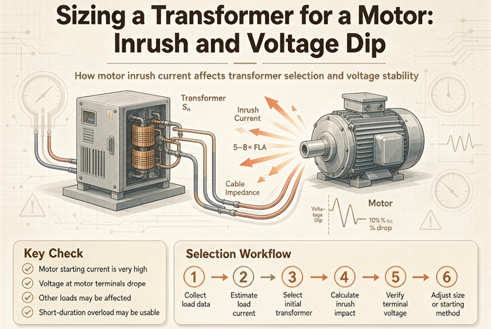
Size the transformer by the voltage dip you can tolerate, not by the motor’s running load. Dip is impedance times starting kVA divided by transformer kVA, so a 1,060 kVA start on a 5.75 percent unit needs 610 kVA for 10 percent, and 780 kVA once 300 kVA is already running on the bus. That works out near 3 kVA per horsepower.
That number surprises people, and the surprise is the reason this question gets asked so often. A 200 hp motor draws about 200 kVA when it runs. The same motor draws 1,060 kVA for the four seconds it takes to come up to speed. Most of the equipment on the plant floor is sized for the first number. The transformer has to survive both.
The trap is that the transformer usually does survive. It carries the starting current without smoking, without tripping, without any of the dramatic failures people worry about. What it cannot do is carry that current at rated voltage. Something else on the bus notices first, a contactor drops out, a drive trips, a PLC reboots, and the start fails in a way that looks like a control problem rather than a sizing problem. By then the transformer is bought and installed.
This article is the arithmetic that keeps you out of that position. One motor, one transformer, one number to hit, and the places where the standard formula quietly gives you a number that is too low.
| The anchor case | Value | Where it comes from |
|---|---|---|
| Motor | 200 hp, 480 V, code F | nameplate |
| Full load current | 240 A | NEC Table 430.250 |
| Locked rotor kVA | 1,060 kVA | 200 hp times 5.3 kVA per hp |
| Locked rotor current | 1,275 A | 1,060,000 divided by 1.732 times 480 |
| Transformer impedance | 5.75 percent | nameplate |
| Load already running when the motor starts | 300 kVA | your load schedule |
| Transformer that holds a 10 percent dip | 1,000 kVA, not 750 | the rest of this article |
Every number in that table is either printed on a nameplate or produced by one division. Nothing in it is a rule of thumb, and that is the point. Transformer sizing for motor loads has a reputation for being a black art because the rules of thumb that circulate are wrong by a factor of three, and the correct method is short enough to do on the hood of a truck.
The short answer is a ratio, not a temperature
Almost every bad answer to this question comes from thinking about the transformer as a thermal device. It is one, but not during a motor start. For the four seconds that matter, the transformer is an impedance, and an impedance does exactly one thing when current flows through it. It drops voltage.
The transformer can supply the current and still fail the start
Here is the calculation that reframes the whole problem. A 1,000 kVA transformer at 5.75 percent impedance delivers 17,391 kVA into a bolted fault. That is 17.4 times its own rating, and it delivers it long enough to operate a breaker. So when a motor asks for 1,060 kVA, which is 1.06 times the transformer rating and 6 percent above it, the transformer is not remotely stressed. It is idling.
The voltage tells a different story. Pushing 1.06 times rated current through an impedance of 5.75 percent drops the terminal voltage by 1.06 times 5.75, which is 6.1 percent. The transformer is fine. The bus is not.
This is why the phrase “transformers can take eight to twelve times nameplate for a few cycles” is true and useless. They can. The question was never whether the winding survives. The question is what the rest of the plant sees while the current flows, and that is governed by impedance, not by thermal mass.
The formula, and the three numbers it needs
The screening calculation is one multiplication and one division.
Voltage dip in percent equals transformer impedance in percent, times motor starting kVA, divided by transformer kVA.
Rearranged, which is how you actually use it:
Transformer kVA must be at least impedance percent, times starting kVA, divided by the dip you are willing to accept.
That is the whole method. It appears in IEEE 399, it is the basis of every motor starting calculator worth using, and it is derived in one line from per unit analysis. At rated current a transformer drops a voltage equal to its impedance. At any other current it drops that fraction of voltage scaled by the current ratio. The motor’s locked rotor current is the current, the transformer’s rating is the base, and the rest is arithmetic.
Three numbers go in. Impedance comes off the nameplate or the submittal, and it is not negotiable after the order. Starting kVA comes off the motor nameplate code letter or the datasheet. The dip limit comes from whatever else is on the bus, and it is the only one of the three that is a decision rather than a fact.
What the formula leaves out
Three things, and all three push the real dip higher than the calculation.
The first is the load already running. The formula treats the transformer as unloaded at the instant the contactor closes. In a plant, it never is. Every running motor, every drive, every heater is drawing current through the same impedance, and that current has already spent part of the voltage budget before the big motor starts. Add the running kVA to the starting kVA and the numerator grows.
The second is the source. The transformer is not connected to an infinite bus. The utility has impedance of its own, the service conductors have impedance, and both sit in series with the transformer winding. In series means the impedances add, which means the dip gets worse, not better. A plant that runs the formula on the transformer alone and gets 6 percent can measure 10 percent on the day the pump starts.
The third is the shape of the current. The formula assumes a sinusoidal current at the system frequency. A motor at standstill has a power factor around 0.2 to 0.3, so the current is almost entirely reactive, and reactive current produces more voltage drop per amp than the arithmetic suggests. The error from this one is smaller than the other two, but it runs in the same direction.
A calculation that ignores all three is a screening check, not an answer. It tells you whether you are in the right neighborhood. For a purchase order, add the running load, add the source, and leave margin.
Step one: get the starting kVA right
Everything downstream depends on this number, and it is the one people get wrong most often, usually by using the motor’s running kVA and a multiplier they half remember.
Read the code letter, then do one division
NEMA MG 1 puts a letter on every motor nameplate that encodes the locked rotor apparent power per horsepower. The letter is not a quality grade and it is not a design class. It is a range, and the range is the answer.
| Code letter | Locked rotor kVA per hp | Midpoint | What usually carries it |
|---|---|---|---|
| A | 0 to 3.15 | 1.57 | rare, special low inrush |
| B | 3.15 to 3.55 | 3.35 | small fractional and low inrush designs |
| C | 3.55 to 4.00 | 3.77 | uncommon |
| D | 4.00 to 4.50 | 4.25 | high slip, hoist and punch press duty |
| E | 4.50 to 5.00 | 4.75 | efficient general purpose |
| F | 5.00 to 5.60 | 5.30 | very common on modern Design B |
| G | 5.60 to 6.30 | 5.95 | the classic Design B industrial motor |
| H | 6.30 to 7.10 | 6.70 | older and lower cost designs |
| J | 7.10 to 8.00 | 7.55 | high inrush, often large frame |
| K | 8.00 to 9.00 | 8.50 | high inrush |
| L | 9.00 to 10.00 | 9.50 | high inrush |
| M | 10.00 to 11.20 | 10.60 | very high locked rotor kVA |
| N | 11.20 to 12.50 | 11.85 | very high locked rotor kVA |
| P | 12.50 to 14.00 | 13.25 | rare, special machines |
The arithmetic is one multiplication. A 200 hp code F motor has a locked rotor apparent power of 200 times 5.3, which is 1,060 kVA. Divide by the square root of three times the voltage and you have locked rotor amps. At 480 V that is 1,275 A.
Which number inside the range you use is a decision with a direction. For the transformer, use the top of the range. The transformer has to survive the worst motor the supplier might ship you, and the code letter is the only guarantee you have. For a breaker trip setting, use the bottom of the range, because a breaker set for the best case nuisance trips on the average motor. Getting these two backwards is a common and expensive mistake.
From 100 hp up, the code letter is almost the inrush multiple
There is a reason the code letter values look like they were chosen to be current multiples, and at 480 V they almost are.
A motor’s full load current in kVA is close to its horsepower rating, because NEMA designs a motor to deliver roughly one horsepower per kVA at full load and 480 V. The table below shows how close.
| Motor | Full load amps | Full load kVA | kVA per hp | Code F as a multiple of full load current |
|---|---|---|---|---|
| 50 hp | 65 A | 54.0 | 1.081 | 4.90 |
| 100 hp | 124 A | 103.1 | 1.031 | 5.14 |
| 200 hp | 240 A | 199.5 | 0.998 | 5.31 |
| 300 hp | 361 A | 300.1 | 1.000 | 5.30 |
| 500 hp | 590 A | 490.5 | 0.981 | 5.40 |
From 100 hp up, the code letter value is within about 3 percent of the inrush multiple of full load current. So a code F motor starts at about 5.3 times its full load current, a code G at about 5.9 times, a code H at about 6.7 times. That is where the folk rule of “six times full load current” comes from, and it is a good rule. It is also why the rule fails on small motors, where the 50 hp column shows 4.9 rather than 5.3.
The shortcut is worth knowing because it lets you sanity check a datasheet in your head. It is not worth using as the primary method, because the code letter is printed on the nameplate and takes ten seconds to read.
When there is no code letter on the nameplate
Older motors, imported motors and a lot of OEM equipment have no code letter. Then you fall back on design letter and experience, and you write down which assumption you used.
A NEMA Design B motor without a code letter is assumed at 6 times full load current for screening. Design C, which has higher starting torque and a double cage rotor, runs higher, and 6.5 to 7 is the safer assumption. Design D, the high slip motor used on hoists and presses, can be 8 to 10 times, and it is genuinely different equipment rather than a conservative version of Design B.
IEC motors have no code letter at all. The equivalent is the locked rotor current ratio in the datasheet, usually written as a multiple of rated current, and for a standard IEC three phase motor it lands between 6 and 8. If the datasheet is missing, 6.5 is a defensible screening assumption for a 4 pole machine and 7.5 for a 2 pole machine, because higher speed machines have longer rotor bars and lower leakage reactance.
The important part is not which number you pick. It is that the number appears in the RFQ, in writing, so the supplier is sizing against the same assumption you are. A transformer quoted against an unstated 4 times inrush and installed behind a motor that draws 8 is the same failure as a wrong calculation, and it is much harder to argue about afterwards.
Locked rotor amps from a datasheet, and why it beats the code letter
When you have real locked rotor amps, use them and throw the code letter away. The code letter is a range that spans 12 percent for code F, and 12 percent on a 1,060 kVA start is 127 kVA, which is a whole transformer size on a small unit.
The conversion is the same division in the other direction. Locked rotor kVA equals the square root of three, times voltage, times locked rotor amps, divided by 1,000. A 200 hp motor with a datasheet figure of 1,310 A at 480 V has a starting kVA of 1,089, which is 2.7 percent above the code F midpoint. Small difference in this case, larger on high inrush designs.
Two cautions on datasheet numbers. The first is voltage. Locked rotor amps are quoted at the motor’s nameplate voltage, which for a 480 V system is usually 460 V, so a datasheet figure needs converting before you compare it with a bus calculation. The second is tolerance. NEMA allows locked rotor current to vary from the published value, and the allowance is not small. If the difference between passing and failing your dip target is 5 percent, you do not have a design, you have a coin flip.
One more number is worth pulling from the datasheet while you are in there, and it is the one almost nobody asks for. The safe stall time, or locked rotor withstand time, tells you how long the motor can sit at locked rotor current before the winding is damaged. It is usually between 10 and 30 seconds for a standard industrial motor, and it is the real limit on how long a start can take. A transformer that holds voltage well enough for the motor to crawl up to speed in 25 seconds has not solved the problem if the motor’s safe stall time is 15.
Step two: pick the dip you can actually live with
The dip limit is the only free variable in the calculation, and it is also the one people accept without thinking. Ten percent gets quoted so often that it reads like a code requirement. It is not. It is an engineering convention that happens to line up with two independent limits, one in the voltage standard and one in the contactor.
Ten percent is a convention with a voltage behind it
Put a 480 V bus at a 10 percent dip and you are at 432 V. ANSI C84.1 Range A sets the utilization voltage floor at 110 V on a 120 V base, which is 91.67 percent, which on a 480 V system is 440 V. Range B extends down to 107 V, which is 428 V.
So a 10 percent starting dip lands at 432 V. That is 8 volts below the Range A floor and 4 volts above the Range B floor. The dip is not a code violation, because C84.1 governs steady state voltage and a motor start is a transient of a few seconds. But it tells you where the edge is, and it explains why the working number is 10 rather than 20. At 20 percent you are at 384 V, which is 80 percent of nominal, and nothing on a plant floor is designed to run there even briefly.
The nameplate wrinkle is worth knowing because it changes how much margin you actually have. Motors on a 480 V system are nameplated 460 V. A bus sitting at nominal is already 104.3 percent of the motor’s rating. A 10 percent bus dip takes the motor to 432 V, which is 93.9 percent of its nameplate, not 90 percent.
| Bus voltage | Percent of 480 V bus | Percent of 460 V nameplate | What it means |
|---|---|---|---|
| 500 V | 104.2 | 108.7 | top of Range A |
| 480 V | 100.0 | 104.3 | nominal, normal |
| 440 V | 91.7 | 95.7 | Range A floor |
| 432 V | 90.0 | 93.9 | a 10 percent dip |
| 428 V | 89.2 | 93.0 | Range B floor |
| 414 V | 86.3 | 90.0 | nameplate minus 10 percent |
| 368 V | 76.7 | 80.0 | where NEMA says a Design B must still accelerate |
Read the bottom two rows together and the picture changes. The motor itself is required by NEMA MG 1 to accelerate its rated load at 80 percent of rated voltage, which is 368 V on a 460 V nameplate, which is a 23 percent dip on the 480 V bus. Nameplate minus 10 percent, the steady state tolerance, is 414 V, a 13.75 percent bus dip.
The motor is not the binding constraint. It tolerates roughly twice the dip that the 10 percent rule allows, and it will happily start at a dip that has already taken out everything else on the bus. That is the single most useful thing to understand about this calculation, because it tells you where to look when a start fails.
The contactor drops out before the motor stalls
A NEMA rated contactor holds in down to about 85 percent of its coil voltage. Below that the magnet cannot keep the armature seated, the contacts open, and the motor is disconnected in the middle of its start.
Eighty five percent of coil voltage is a 15 percent dip, and the coil is fed from the same bus the motor is dragging down. So a 15 percent bus dip is exactly the point where the starter lets go. Not 20 percent, not 25. Fifteen. And the failure is not graceful. The motor is at speed, drawing 400 percent of full load current, the contactor opens, the motor coasts, and if the control circuit has a restart feature it tries again into a still loaded system.
This is why so many “the transformer is too small” complaints are actually contactor complaints. The motor would have made it. The coil would not.
There is a cheap fix that is worth mentioning because it is so often missed. A contactor with a 120 V coil fed from a control transformer with taps can be set to hold at a lower bus voltage, and some starters are available with wide range electronic coils that ride through a 30 percent dip. If the only thing failing is the contactor, the answer may be a different coil rather than a bigger transformer. Check that before you spend six figures on kVA.
Torque falls with the square of what is left
Motor torque is proportional to the square of applied voltage. That square is the reason a modest dip becomes a starting problem rather than a voltage quality problem.
| Voltage dip | Voltage remaining | Torque remaining | What starts reliably |
|---|---|---|---|
| 0 percent | 100 percent | 100 percent | everything |
| 5 percent | 95 percent | 90 percent | everything |
| 10 percent | 90 percent | 81 percent | centrifugal pumps, fans, unloaded conveyors |
| 15 percent | 85 percent | 72 percent | pumps and fans, marginal for a loaded conveyor |
| 20 percent | 80 percent | 64 percent | the NEMA floor, nothing with a hard start |
| 25 percent | 75 percent | 56 percent | nothing designed for it |
| 30 percent | 70 percent | 49 percent | the motor stalls and the overload trips |
The table explains why the load type matters as much as the motor. A centrifugal pump’s torque requirement rises with the square of speed, so at low speed it needs almost nothing and the motor has enormous margin. A conveyor or a positive displacement compressor needs roughly constant torque from the first revolution, so it needs full rated torque at zero speed, and a 19 percent torque reduction is a real problem rather than a margin question.
A loaded conveyor at 81 percent torque will usually still start, because a Design B motor’s breakdown torque is 200 percent or more of rated and the locked rotor torque is around 150 percent. A conveyor at 64 percent torque is a different conversation, and the honest answer is that you should not be starting it direct on line at any dip you would accept on a shared bus.
What a drive does with the dip
A variable frequency drive is often proposed as the fix, and for the motor side it is. The drive limits starting current to 110 or 150 percent of full load, which cuts the starting kVA by a factor of four, and the dip with it.
The drive is also a load that is sensitive to the dip it creates for everything else, which is the part people miss. A 480 V drive rides through a supply dip only for as long as its DC bus capacitors hold. At full load that is typically three to five cycles, which is 50 to 83 milliseconds. A motor start lasts seconds. So a drive on the same bus will trip at a dip that a contactor would have survived, and it will trip early in the start when the dip is deepest.
Undervoltage relays are the same story with a different number. Protection relays are often set to trip at 80 or 85 percent of nominal, which is a 15 to 20 percent dip, and the trip is usually instantaneous with no time delay to ride through a start.
The practical consequence is that a bus with drives on it has a tighter dip limit than a bus with only motors, and the limit is set by the ride-through of the most sensitive load rather than by the motor. Ten percent is a reasonable number for a motor bus. For a bus with drives, 5 to 8 percent is more realistic, and that changes the transformer size by a full step.
Step three: turn the dip target into a kVA number
Now the arithmetic collapses into one table, and this is the table worth keeping.
The ratio table that replaces the rule of thumb
Rearrange the formula and the answer becomes a ratio. Transformer kVA divided by starting kVA equals impedance divided by the dip limit.
| Impedance | 5 percent dip | 8 percent dip | 10 percent dip | 12 percent dip | 15 percent dip |
|---|---|---|---|---|---|
| 4.0 percent | 0.800 | 0.500 | 0.400 | 0.333 | 0.267 |
| 5.75 percent | 1.150 | 0.719 | 0.575 | 0.479 | 0.383 |
| 6.5 percent | 1.300 | 0.812 | 0.650 | 0.542 | 0.433 |
Read the 5.75 percent row at 10 percent dip and you get 0.575. The transformer has to be 57.5 percent of the starting kVA. For a 1,060 kVA start that is 610 kVA, and the next standard size up is 750.
Two rows in that table are worth staring at. At 4 percent impedance and a 5 percent dip target, the ratio is 0.80, which means the transformer has to be four fifths the size of the start. At 6.5 percent impedance and the same 5 percent target, the ratio is 1.30, which means the transformer has to be bigger than the motor’s starting demand. That is not a design, it is an admission that the dip target is wrong for the application. If your calculation keeps telling you to buy a transformer larger than the motor’s inrush, stop and change something else.
Translate the ratio into kVA per horsepower and it turns into a rule of thumb you can actually use. At 5.75 percent impedance, a 10 percent dip, and a code F motor, the answer is 3.05 kVA per horsepower. At 15 percent dip it is 2.03. At 4 percent impedance and 10 percent dip it is 2.12.
| Impedance | 10 percent dip, DOL | 15 percent dip, DOL | 10 percent dip, soft start | 10 percent dip, VFD |
|---|---|---|---|---|
| 4.0 percent | 2.12 kVA/hp | 1.41 kVA/hp | 1.00 kVA/hp | 0.48 kVA/hp |
| 5.75 percent | 3.05 kVA/hp | 2.03 kVA/hp | 1.44 kVA/hp | 0.69 kVA/hp |
| 6.5 percent | 3.44 kVA/hp | 2.30 kVA/hp | 1.63 kVA/hp | 0.78 kVA/hp |
The old rule of one kVA per horsepower is not a rule, it is a running load statement. It is correct for the motor and wrong for the transformer by a factor of three. The 3 kVA per horsepower figure in the table is where the rule of thumb should have been all along, and it only appears when the dip target, the impedance and the code letter are all stated.
A 200 hp motor on a bus that is already loaded
Run the anchor case with the numbers from the top of this article. A 200 hp code F motor, 1,060 kVA of starting demand, a 10 percent dip target, 5.75 percent impedance, and 300 kVA of other load already running.
The numerator is 1,060 plus 300, which is 1,360. Multiply by 5.75 and divide by 10, and the answer is 782 kVA. The next standard size is 1,000 kVA.
Now go the other way and check what the candidates actually do.
| Transformer | Impedance | Dip with a 1,060 kVA start | Dip with 300 kVA already running | Verdict |
|---|---|---|---|---|
| 500 kVA | 5.75 percent | 12.19 percent | 15.64 percent | contactor drops out |
| 750 kVA | 5.75 percent | 8.13 percent | 10.43 percent | misses 10 percent |
| 1,000 kVA | 5.75 percent | 6.10 percent | 7.82 percent | holds |
| 1,500 kVA | 5.75 percent | 4.06 percent | 5.21 percent | overbuilt |
| 750 kVA | 4.0 percent | 5.65 percent | 7.25 percent | holds, see below |
The 750 kVA column is the interesting one. On an empty transformer it passes at 8.13 percent, which is why a supplier sizing on the motor alone will quote it and be arithmetically correct. Add the 300 kVA that is genuinely running, and the same transformer lands at 10.43 percent. It fails by half a point, on a piece of equipment that costs a six figure sum and has a 16 to 20 week lead time.
The impedance lever in the last row is worth a paragraph of its own, and it gets one later. At 4 percent impedance the 750 kVA unit holds 7.25 percent with the 300 kVA running, which passes. So the choice is not automatically “buy the bigger box”. It is “buy the bigger box or specify the lower impedance”, and those two options have very different consequences downstream.
What the load already running costs you
The pre-load term is the one people skip, and it is easy to state as a ratio so you never skip it again.
At 5.75 percent impedance and a 10 percent dip target, every 100 kVA of load running when the motor starts costs 57.5 kVA of transformer. Three hundred kVA costs 172.5 kVA, which is why the answer moved from 750 to 1,000.
At a 15 percent dip target the same 300 kVA costs 115 kVA, so the pre-load is less than half as expensive. At 4 percent impedance and 10 percent it costs 120 kVA. The cost of pre-load is proportional to impedance and inversely proportional to the dip you accept, exactly like everything else in this calculation.
The operational lesson is more useful than the arithmetic. A plant that starts its largest motor during a quiet shift has a smaller dip than the same plant starting it at peak. If the load schedule has any flexibility, the cheapest transformer upgrade is often a start sequence change, and it costs nothing but a line of PLC logic.
The same motor at 208, 480 and 600 volts
Starting kVA is a property of the motor, not of the system it is connected to. A 200 hp code F motor demands 1,060 kVA whatever the bus voltage is, because the code letter is expressed per horsepower and horsepower does not change. What changes is the impedance a transformer of that class typically has, and that changes the answer.
| System voltage | Typical impedance for the size | Start kVA | Transformer for 10 percent dip | Fault current at that size | Gear class |
|---|---|---|---|---|---|
| 208 V | 4.0 percent | 1,060 kVA | 500 kVA | 34,697 A | 35 kA |
| 480 V | 5.75 percent | 1,060 kVA | 750 kVA | 15,689 A | 18 kA |
| 600 V | 5.75 percent | 1,060 kVA | 750 kVA | 12,551 A | 14 kA |
Two things fall out of that table, and they point in opposite directions.
At 208 V the typical dry type impedance is lower, around 4 percent rather than 5.75, because small low voltage windings are built with less leakage reactance. That lower impedance lets a 500 kVA unit hold 8.48 percent on the same 1,060 kVA start, which is a transformer size smaller than the 480 V answer. It looks like a free lunch until you check the fault current. A 500 kVA transformer at 208 V delivers 34,697 A, which is 35 kA gear, more than double the 18 kA class the 480 V case needs. You saved a transformer size and spent it on switchgear, and the switchgear is the more expensive of the two.
At 600 V the transformer size is identical to 480 V and the fault current is 20 percent lower, which drops the gear a class. That is the whole engineering argument for 600 V systems in a sentence. Same transformer, same dip, cheaper gear, and 30 to 40 percent less copper in the feeder for the same ampacity.
When the answer is no transformer at all
There is a point where the arithmetic stops being advice and starts being a warning, and it usually arrives around 500 hp at 480 V.
A 500 hp code F motor has a starting demand of 2,650 kVA. At 10 percent dip and 5.75 percent impedance with no pre-load, that needs 1,524 kVA, which is a 2,000 kVA transformer. Add 300 kVA of running load and the requirement goes to 1,696 kVA, still 2,000. So far so ordinary.
Then check the fault current. A 2,000 kVA transformer at 5.75 percent delivers 41,837 A at 480 V. That is beyond the 42 kA class by a hair and well past the 35 kA class, so every switchboard, panel and breaker downstream has to be rated 65 kA. The transformer grew by a factor of four to serve one motor, and the switchgear grew with it.
At that point the honest options are not transformer sizes. They are a soft starter, which drops the starting kVA to about 1,250 and the requirement to 720 kVA, or a 2,300 V motor with its own transformer, or a drive. A supplier who quotes the 2,000 kVA unit without mentioning any of that has answered the question you asked rather than the question you have.
The impedance you cannot see
Two hidden impedances sit in series with the transformer winding, and both make the real dip worse than the calculation.
The utility is in series with your transformer
The screening formula uses the transformer’s impedance and stops. The real circuit is the utility source, the service conductors, and the transformer, all in series, and impedances in series add.
Put the numbers on a 1,000 kVA transformer at 5.75 percent with a 1,060 kVA start and 300 kVA running. Convert the utility to the same base and add.
| Utility fault level | Source impedance on a 1,000 kVA base | Total impedance | Dip, start only | Dip with 300 kVA running |
|---|---|---|---|---|
| 25 MVA | 0.0400 | 0.0975 | 10.34 percent | 13.26 percent |
| 50 MVA | 0.0200 | 0.0775 | 8.21 percent | 10.54 percent |
| 100 MVA | 0.0100 | 0.0675 | 7.16 percent | 9.18 percent |
| 250 MVA | 0.0040 | 0.0615 | 6.52 percent | 8.36 percent |
| effectively infinite | 0.0000 | 0.0576 | 6.11 percent | 7.83 percent |
The transformer-only figure is 6.10 percent. The bottom row of the table is 6.11, which confirms the screening formula. The realistic 50 MVA row is 8.21, and with the pre-load it is 10.54, which fails the target the transformer alone appeared to pass.
That is a 72 percent error between the screening number and the realistic one, on a calculation that takes four lines. It is the single largest source of undersized motor transformers in practice, and it is invisible unless you ask the utility for the fault level at the service point.
Ask for it in writing. Utilities publish it, most will provide it on request for a specific address, and the number you want is the three phase available fault current at the service, not at the substation. A 25 MVA source is a long rural feeder. A 250 MVA source is a substation a few blocks away. The difference between those two is more than a transformer size.
The limit at the service point that overrides the one at the bus
There is a second dip limit and it is not yours to set. Utilities limit voltage flicker at the point of common coupling, because a motor start at one customer’s plant is a voltage dip in the neighbor’s building. IEEE 1453 is the standard behind those limits, and the practical form is a cap on the voltage change a customer’s load can impose on the shared service.
The caps vary by utility and by feeder, and 3 to 5 percent at the service point is the range you will meet most often. Run the arithmetic against 3 percent and the conclusion is uncomfortable. A 1,060 kVA start that produces a 3 percent dip at the service point implies 35,333 kVA of source capacity. At 5 percent it implies 21,200 kVA. No transformer you can buy changes those numbers, because the limit is on the source side of the transformer, and the transformer is only part of the impedance the utility sees.
What that means in practice is that the transformer calculation has a ceiling that is not about the transformer. If the utility’s flicker limit is the binding constraint, the only fixes are on the motor side. Reduced voltage starting, a soft starter, a drive, or a smaller motor. Buying kVA makes the dip at your bus better and leaves the dip at the service point almost unchanged, because the utility’s impedance dominates once the transformer gets large.
Run both calculations. The bus number tells you whether your own equipment will survive the start. The service point number tells you whether the utility will let you do it at all, and it is the one that can stop a project after the equipment is ordered.
Starting methods, ranked by what they do to the transformer
If the dip target is fixed by the rest of the plant, the only variables left are the transformer and the starter. The starter is almost always the cheaper of the two, and it is the one people reach for last.
| Starting method | Starting current, times full load | Starting kVA for 200 hp | Transformer for 10 percent dip at 5.75 percent | Torque available |
|---|---|---|---|---|
| Direct on line | 5.3 | 1,060 kVA | 750 to 1,000 kVA | 100 percent |
| Autotransformer, 80 percent tap | 3.39 | 678 kVA | 500 kVA | 64 percent |
| Autotransformer, 65 percent tap | 2.24 | 448 kVA | 300 kVA | 42 percent |
| Star-delta | 1.77 | 354 kVA | 225 kVA | 33 percent |
| Soft starter | 2.5 | 500 kVA | 300 kVA | 60 to 80 percent, ramped |
| Variable frequency drive | 1.2 | 240 kVA | 150 kVA | 100 percent or more |
The table makes the trade obvious. Dropping from direct on line to a soft starter cuts the required transformer from 1,000 kVA to 300 kVA, which is a bigger saving than any impedance choice, and it does it without touching the fault current.
The tap arithmetic behind an autotransformer
An autotransformer starter reduces the voltage applied to the motor by a fixed fraction, and both the line current and the torque fall with the square of that fraction. It is the cleanest of the reduced voltage methods because the relationship is exact.
An 80 percent tap puts 80 percent of line voltage on the motor, so the motor current falls to 80 percent, and the line current falls to 64 percent because the autotransformer’s own transformation ratio applies on top. Torque falls to 64 percent, the same as the current.
| Tap | Motor voltage | Line current | Torque |
|---|---|---|---|
| 50 percent | 50 percent | 25 percent | 25 percent |
| 65 percent | 65 percent | 42.25 percent | 42.25 percent |
| 80 percent | 80 percent | 64 percent | 64 percent |
The 65 percent tap is the standard choice for a pump or a fan, because 42 percent torque is enough for a centrifugal load and 42 percent current cuts the transformer requirement by more than half. The 80 percent tap is for loads that need most of their breakaway torque, and at 64 percent current it still saves a transformer size.
Two practical cautions. The first is that an autotransformer starter is a tapped winding, so it has its own inrush and its own short circuit contribution, and it needs protection sized for both. The second is that the transition from the reduced tap to full voltage is a second current transient, and on a large motor it can produce a dip nearly as deep as the original start if the transition happens too early. Set the transition on current, not on a timer.
What star-delta really costs
Star-delta is the cheapest reduced voltage starter and the most misunderstood. It puts the motor windings in star during the start, which applies 58 percent of line voltage across each winding, and it delivers one third of the direct on line current and one third of the torque.
Thirty three percent torque is enough for a fan, which needs almost nothing at low speed, and for an unloaded centrifugal pump. It is not enough for a loaded conveyor, a positive displacement compressor, or a crusher, and specifying it there produces a motor that sits at locked rotor current and trips on overload every time.
The other cost is motor terminals. Star-delta needs six leads brought out of the motor, which means a motor that is ordered for it rather than a motor that is adapted. Retrofitting is not possible on a three lead machine, and a lot of large motors are three lead.
There is also a transition transient, the same as the autotransformer, and it is worse on star-delta because the open transition briefly disconnects the motor from the supply while it is still generating back EMF. A closed transition starter solves it and costs more. On a weak bus the open transition dip can exceed the starting dip, which is a hard thing to explain after the fact.
Where a soft starter wins and where it does not
A soft starter uses thyristors to ramp the voltage up over a settable time, which limits the current to somewhere between 250 and 400 percent of full load. It is the best compromise for most industrial motor loads because it keeps most of the torque, gives a smooth acceleration, and needs no motor modification.
For transformer sizing the number to use is 250 percent of full load, which is 2.5 kVA per horsepower, which produces the 1.44 kVA per horsepower transformer figure in the earlier table. That is a 300 kVA transformer for a 200 hp motor, down from 1,000.
Three things a soft starter does not fix. It does not reduce the fault current, so the switchgear rating is unchanged. It does not eliminate the dip entirely, and the arithmetic is worth following. Five hundred kVA of starting demand on the 300 kVA unit the soft starter just paid for is a 9.6 percent dip, which is right at the target and not comfortably inside it. And it introduces harmonics during the ramp, which matters if there are capacitors on the bus, because a soft starter and a capacitor bank interact badly.
The last one catches people out. A power factor correction bank sized for the plant’s running load becomes a resonance problem the moment a soft starter is ramping nearby, and the failure mode is a capacitor failure rather than a voltage problem. If the plant has fixed capacitors, check before specifying a soft starter.
The cost you did not budget for: fault current
Every kVA you add to fix a dip adds fault current at the same time, and the second cost lands on the switchgear rather than the transformer.
One kVA step is one gear class
Fault current at the transformer secondary is full load current divided by per unit impedance. Raise the kVA and you raise the current twice, once through the kVA term and once through nothing at all, because the impedance percentage stays the same.
| Transformer | Impedance | Full load amps at 480 V | Fault current | Gear class needed |
|---|---|---|---|---|
| 750 kVA | 5.75 percent | 902 | 15,689 A | 18 kA |
| 1,000 kVA | 5.75 percent | 1,203 | 20,918 A | 22 kA |
| 1,500 kVA | 5.75 percent | 1,804 | 31,378 A | 35 kA |
| 750 kVA | 6.5 percent | 902 | 13,879 A | 14 kA |
| 1,000 kVA | 6.5 percent | 1,203 | 18,505 A | 22 kA |
Read the first two rows together. Going from 750 to 1,000 kVA to fix a 10.43 percent dip raises fault current from 15,689 A to 20,918 A, which is 33 percent, and it moves the required switchgear from the 18 kA class to the 22 kA class. Every panel, every breaker, every disconnect downstream has to be re-rated or replaced.
On a new installation that is a line item in the gear specification and it is easy to absorb. On a retrofit it can exceed the cost of the transformer, because the existing gear is already installed, already inspected and already energized, and replacing it means a shutdown.
That is the practical reason the impedance lever exists, and it is worth understanding before you use it.
Impedance as a lever, with a price on the other end
At 4 percent impedance, a 750 kVA transformer holds 7.25 percent dip with 300 kVA running, which passes a 10 percent target without buying a bigger unit. That looks like free money. It is not.
Lower impedance means higher fault current, in exactly the same proportion. A 1,000 kVA unit at 4 percent delivers 30,070 A, which is the 35 kA class, up from 22 kA. It also means higher mechanical forces on the windings during a short circuit, which is why low impedance units are built with more bracing and cost more per kVA than the standard product.
The honest way to use impedance is as a specified target with a tolerance, not as a wish. Write “5.75 percent, plus or minus 7.5 percent of the nominal value” in the RFQ, or whatever tolerance your fault study can absorb. A supplier who delivers 4 percent against a 5.75 percent request has changed your fault current by 44 percent, and if the gear was rated on the nominal figure, that is a problem you find at commissioning.
There is one more consequence, and it is the reason impedance is the last lever rather than the first. Lower impedance raises the transformer’s contribution to a fault on the primary side too, through the winding ratio, and it raises the through fault current that the primary protection has to be able to clear. A transformer whose primary fuse cannot distinguish a fault from an energization is a transformer that trips the feeder every time the plant restarts after an outage.
Thermal duty: the constraint that rarely binds
The folklore says repeated motor starts cook transformers. The arithmetic says otherwise for anything above a few hundred kVA, and the reason is worth going through because it frees you to stop worrying about the wrong thing.
How many starts a transformer actually tolerates
Winding heating is proportional to current squared, and a start lasts seconds. Compare the start’s heating to the transformer’s thermal time constant and the answer is small.
The 1,000 kVA unit in the anchor case has a full load current of 1,203 A. The motor’s start pushes 1,275 A through it, which is 1.06 times rated, so the heating rate during the start is 1.12 times rated. A start lasts about four seconds, so it deposits the equivalent of 4.5 seconds of full load heating.
A 1,000 kVA dry type transformer has a thermal time constant on the order of 45 minutes, which is 2,700 seconds. One start is 0.17 percent of a time constant. Six starts an hour is 1 percent. You would need roughly 600 starts an hour, continuously, to reach the point where the winding temperature climbs at all, and no motor on a plant floor starts 600 times an hour.
The small transformer case is tighter but still not binding. A 15 kVA unit starting a 5 hp motor sees 35.8 A against its own 18.0 A rating, which is 1.98 times rated, so the heating rate during the start is 3.9 times rated. Three seconds of that is 11.8 rated-seconds against a time constant around 20 minutes, which is 1 percent per start and 5.9 percent for six starts an hour.
So the thermal answer is: not a constraint, at any size, for any realistic starting frequency. Which means the dip calculation is the only one that matters, and the effort spent on “can it take the inrush” is effort spent on the wrong question.
When the thermal limit does bind
There are three cases where it does, and they are worth knowing because they are the ones where the usual answer fails.
The first is high inertia loads. A centrifuge, a large fan with a heavy impeller, or a ball mill can take 30 to 60 seconds to accelerate, and during that time the current stays near locked rotor. Sixty seconds at 1.06 times rated is 67 rated-seconds, which is 2.5 percent of a time constant per start. Still not catastrophic, but with four starts an hour it becomes a design input rather than a rounding error.
The second is a motor that fails to accelerate. A motor that sits at locked rotor current because the load is too heavy produces heat continuously, and the transformer’s contribution climbs every second. The motor’s overload protection is supposed to clear it, and the transformer’s thermal capacity is a race against that protection. This is the case where an undersized transformer genuinely fails, and it fails because the motor never got to speed rather than because the start was frequent.
The third is a transformer with an air cooled rating only. A unit rated AN with no forced cooling has less thermal margin than an AN/AF unit, and the difference shows up in exactly the long start case.
More than one motor on the bus
Plants rarely have one motor, and the single motor method needs one adjustment to handle a group.
Who is running and who is starting
The rule is short. Every motor that is running when the largest motor starts counts as pre-load, at its running kVA. Every motor that starts at the same instant as the largest motor adds to the starting kVA.
A 200 hp motor starting while a 150 hp motor runs: the 200 hp contributes 1,060 kVA of starting demand, the 150 hp contributes 795 kVA of running demand, and with 300 kVA of other load the numerator is 2,155. At 5.75 percent and 10 percent dip the requirement is 1,239 kVA, so the answer is 1,500 kVA rather than 1,000.
| Scenario | Starting kVA | Running kVA | Numerator | Transformer for 10 percent dip |
|---|---|---|---|---|
| 200 hp alone, empty bus | 1,060 | 0 | 1,060 | 750 kVA |
| 200 hp alone, 300 kVA running | 1,060 | 300 | 1,360 | 1,000 kVA |
| 200 hp starts, 150 hp running | 1,060 | 795 | 1,855 | 1,500 kVA |
| 200 plus 150 starting together | 1,855 | 0 | 1,855 | 1,500 kVA |
The last two rows land on the same transformer, which is not a coincidence and is worth understanding. A motor that starts at the same instant contributes its starting kVA. A motor that is already running contributes its running kVA. A 150 hp motor’s running kVA is 150, and its starting kVA is 795, so the two cases differ by 645 kVA in the numerator. They land on the same standard size here because the gap between 1,000 and 1,500 is wide enough to absorb it. On a smaller unit they would not.
The operational point is that simultaneous starting is much worse than sequential starting, and the fix is a start interlock rather than a bigger transformer. Two large motors that start within a second of each other produce a dip that neither produces alone, and the interlock that prevents it costs a timer.
The largest motor rule, and what it does not cover
NEC 430.24 sizes feeder conductors for 125 percent of the largest motor plus 100 percent of the rest, and that rule gets applied to transformers by habit. It is not the same calculation and it does not produce the same answer.
Run it on the anchor case and 125 percent of 200 hp plus 100 percent of 300 kVA gives 550 kVA, which is a 750 kVA transformer. The dip calculation on the same case gives 1,000 kVA. The code minimum is 750 and the engineering answer is 1,000, and the difference is entirely the starting transient.
That gap is normal and it is not a code violation. NEC 430.24 is a conductor ampacity rule, and ampacity is a thermal question. It says nothing about voltage during a start. A design that meets the code and fails the start is a design that met the wrong requirement.
There is one place in the code where a starting dip limit does appear, and it is worth knowing because it is the exception that proves the rule. NEC 695.7 requires the voltage at a fire pump controller to stay within 15 percent of normal during motor starting, and within 5 percent at 115 percent of full load current. That is the only explicit numeric dip limit in the code for a motor start, and it applies to fire pumps because a fire pump that fails to start is a life safety failure rather than an inconvenience.
If your motor is a fire pump, 695.7 is the governing rule and 15 percent is your number. If it is anything else, the 10 percent figure is an engineering convention and you should write down where it came from rather than treating it as a requirement.
What to put in the RFQ
Most motor transformer quotes are wrong because the RFQ did not contain enough for a right answer, not because the supplier made a mistake.
The five lines that get you a real answer
Write these five lines into the RFQ and the quote will be defensible.
- Motor horsepower, voltage and nameplate code letter, or locked rotor amps from the datasheet.
- The running load on the transformer when the motor starts, in kVA, and which loads are included.
- The dip limit and where it came from, whether that is a plant standard, a utility requirement, or the ride-through of a specific drive.
- The available fault current at the service point, from the utility, in writing.
- The starting method, and whether it is fixed or open.
Line three is the one that changes the answer most and is the one most often missing. “Size it for a motor load” produces a quote for whatever the supplier’s default assumption is, and the default is usually a 10 percent dip on an empty transformer, which is optimistic on both counts.
Line four is the one that gets skipped because it takes a phone call. It is also the line that decides whether your 22 kA gear is adequate or the whole lineup has to change.
What a supplier should send back
A useful quote comes with the arithmetic, not just the kVA. Ask for the submittal to include the impedance, the calculated dip at the stated running load, the fault current at the secondary terminals, and the basis for the impedance tolerance.
If a supplier cannot produce the dip calculation, they are quoting a transformer rather than a system, and the difference shows up at commissioning. It is a reasonable question to ask at the quotation stage, and a supplier who does the calculation will usually volunteer it.
One more item belongs in the submittal and almost never is: the impedance tolerance. A 5.75 percent nominal unit is normally guaranteed within plus or minus 7.5 percent, which is 5.32 to 6.18 percent. The dip you calculated at 5.75 could be 8.2 percent at 6.18 on the same transformer, and if your margin was 0.3 percent you did not have margin.
Five mistakes that survive commissioning
The first is sizing on the motor’s running kVA. A 200 hp motor looks like 200 kVA and needs 1,060 kVA for four seconds, a factor of 5.3 that no amount of “add 25 percent for starting” covers.
The second is ignoring the load already running. The same transformer that passes at 8.13 percent on an empty bus sits at 10.43 percent with 300 kVA on it, and the difference is the whole margin.
The third is ignoring the source impedance. The transformer-only calculation gave 6.10 percent; with a 50 MVA utility and the running load it is 10.54 percent. Both numbers are correct, and only one of them describes the installation.
The fourth is treating the 10 percent figure as a code requirement. It is a convention that lines up with the Range A voltage floor and the contactor hold-in point, and on a bus with drives it is too generous, while on a dedicated feeder with nothing else on it, 15 percent is defensible and cheaper.
The fifth is buying kVA to solve a contactor problem. If the motor would have started and the starter dropped out, a wide range coil or a different control transformer tap solves it for a fraction of the cost of a transformer size.
FAQ
How do you size a transformer for a motor start?
Multiply the motor’s horsepower by its NEMA code letter value in kVA per hp to get starting kVA. Multiply that by the transformer impedance in percent and divide by the dip you will accept. A 200 hp code F motor at 5.3 kVA per hp is 1,060 kVA, and at 5.75 percent impedance and a 10 percent dip the answer is 610 kVA. Add the load already running before you do the division.
Where do I find the locked rotor kVA of a motor?
On the nameplate, as a single letter. NEMA MG 1 assigns each letter a range of locked rotor kVA per horsepower, and code F is 5.0 to 5.6, code G is 5.6 to 6.3, code H is 6.3 to 7.1. Multiply the letter’s value by the horsepower. If the nameplate has no code letter, use the datasheet’s locked rotor amps and convert with 1.732 times voltage times amps divided by 1,000.
How much voltage dip is acceptable during motor starting?
Ten percent is the common target, and it comes from two independent limits rather than from a code. A 10 percent dip on a 480 V bus lands at 432 V, just below the 440 V floor of ANSI C84.1 Range A, and a 15 percent dip is where a NEMA contactor’s coil drops out. Motors themselves tolerate more, because NEMA MG 1 requires a Design B motor to accelerate rated load at 80 percent of rated voltage.
Does a bigger transformer reduce the motor’s inrush?
No. The motor draws the same locked rotor current regardless of the transformer behind it, because inrush is set by the motor’s own impedance. A bigger transformer reduces the voltage dip that the inrush causes, which is what makes the start succeed, but the current at the motor terminals is unchanged. That is why a bigger transformer does not help with a breaker that trips on inrush.
Can a transformer start a motor larger than its own rating?
Thermally yes, and this is where the folklore comes from. A 1,000 kVA transformer carries a 1,060 kVA start at 1.06 times rated current for four seconds without measurable heating, which is 0.17 percent of its thermal time constant. It fails on voltage rather than temperature, because 1.06 times rated current through 5.75 percent impedance is already a 6.1 percent dip before anything else on the bus is counted.
What is the kVA per horsepower rule for motor transformers?
About 3 kVA per horsepower for a direct on line start, 5.75 percent impedance, and a 10 percent dip target, using a code F motor. At a 15 percent dip target it drops to 2 kVA per horsepower, at 4 percent impedance and 10 percent dip it is 2.1, and with a soft starter at 10 percent dip it is 1.4. The old figure of 1 kVA per horsepower describes the running load and understates the transformer by a factor of three.
Why does the contactor drop out when the motor starts?
Because the coil sees the same voltage dip the motor does. A NEMA rated contactor holds in to about 85 percent of coil voltage, so a 15 percent bus dip puts the coil at its drop-out threshold and the contacts open. The motor is usually capable of finishing the start. The starter is not, and the fix is often a wide range electronic coil rather than a larger transformer.
What does a soft starter do to transformer sizing?
It cuts the starting kVA to about 250 percent of the motor’s running kVA, which drops the transformer requirement from 3 kVA per horsepower to about 1.4 at a 10 percent dip target. For a 200 hp motor that is 300 kVA instead of 1,000. It does not reduce fault current, so the switchgear rating is unchanged, and it introduces harmonics during the ramp.
Should I use 750 kVA or 1,000 kVA for a 200 hp motor?
It depends on what is running when the motor starts. On an empty transformer, 750 kVA gives an 8.13 percent dip and passes a 10 percent target. With 300 kVA of other load running, the same unit gives 10.43 percent and fails. The threshold is 782 kVA, so any running load above about 290 kVA pushes the answer to 1,000 kVA.
Does the utility limit how much my motor start can dip the voltage?
Yes, and the limit is at the service point rather than at your bus. Utilities cap the voltage change a customer’s load imposes on the shared feeder, with 3 to 5 percent being the range you meet most often, and IEEE 1453 is the standard behind the analysis. A 1,060 kVA start at a 3 percent limit implies 35,333 kVA of source capacity, which no transformer purchase can supply.
Free: Transformer Specification Checklist
The exact RFQ sheet our engineers use — send it and get a quoted proposal within 24h.
Download checklist