Four numbers on a dry-type nameplate decide everything else: kVA, temperature rise, ambient and cooling. Change one and the kVA changes. A 1,000 kVA unit at 50 °C, 2,000 m and K-13 load is really 819 kVA, and that is 23 kVA short of an 800 kW load, which puts you on a 1,500 kVA frame.
That is the whole problem in one sentence. A dry-type transformer is sold as a box rated in kVA, and it is actually a thermal machine rated in degrees. The kVA is a promise about how hot the winding gets, and the promise is conditional on an ambient temperature, an altitude, a fan state and a harmonic spectrum. Every one of those conditions is somebody else’s decision. The mechanical engineer picks the room temperature. The site picks the elevation. The load picks the harmonics. You are left holding a nameplate that says 1,000 kVA and an installation that can use 819.
The second half of the problem is the room. Dry-type transformers exist because they make the room possible. No oil means no containment, no drainage, no vault, no deluge. That is the product. Then the electrical code draws a line at 112.5 kVA and asks for a fire-rated room anyway, which is the exact thing the dry-type was supposed to avoid, and a surprising number of buyers find out at permit review.
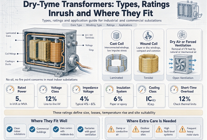
This article sorts the subject into three parts that answer three different questions. Types: what is inside the box, and what each construction is actually protecting. Ratings: the four numbers and how they interact, so the nameplate stops being a mystery. Where they fit: the room, the enclosure, the voltage ceiling and the handful of applications that look right and are not.
| The anchor case | Value | Where it comes from |
|---|---|---|
| Rating | 1,000 kVA, 480 V delta primary, 208Y/120 V secondary | the order |
| Full load current, secondary | 2,776 A | 1,000,000 divided by 1.732 times 208 |
| Full load current, primary | 1,203 A | 1,000,000 divided by 1.732 times 480 |
| Impedance | 5.75 percent | nameplate |
| Available fault current, secondary | 48,273 A | 2,776 divided by 0.0575, which is above 42 kA and below 65 kA |
| No-load loss | 1,500 W | the efficiency table |
| Load loss at rated current | 9,000 W | the efficiency table |
| Heat into the room at full load | 10.5 kW, about 3 tons of cooling | 1,500 plus 9,000 |
| Usable capacity in a 50 °C room at 2,000 m on K-13 load | 819 kVA | the derating chain |
| Room requirement | fire-rated room above 112.5 kVA, with exceptions | NEC 450.21(B) |
Every number in that table is either printed on a document you already have or produced by one division. The parts that are not printed anywhere are the conditions attached to the kVA, and those are the parts this article is about.
The whole article in one idea
A transformer rating is not a power limit. It is a temperature promise with four conditions attached.
The winding has an insulation system with a temperature limit. The limit is reached by adding three things: the air temperature around the unit, the rise the winding produces at rated current, and a gradient that accounts for the hottest spot inside the coil being hotter than the average. Ambient plus rise plus gradient equals the limit. That is the entire rating system, and it is why the same physical core and coil can be sold at three different kVA numbers depending on which rise class the factory designed it for.
Once you see the rating that way, the rest of the article is bookkeeping. Types are different ways of protecting the winding from the air around it. Cooling classes are different ways of getting heat out of the winding faster. Derating factors are adjustments to the ambient term. The room and the enclosure are the same question asked in a different language: what is the air like where this thing will live.
What “type” means, and why the usual list is incomplete
Search this subject and you get a list: cast resin, VPI, open wound, sometimes a fourth entry about gas. The list is not wrong, it is just sorted on one axis and presented as if it were the only one. Four axes matter, and a purchase order needs all four.
Axis one is how the winding is protected. Bare copper with a varnish dip, varnish driven in under vacuum and pressure, or epoxy cast around the coil in a mold. This is what people mean by type, and it decides how the unit behaves in humid, dirty or corrosive air.
Axis two is how the heat leaves. Natural convection, fans, or fans that cycle on a thermostat. This decides the kVA you can actually pull out of a given frame, and it is the cheapest capacity you will ever buy.
Axis three is what the enclosure keeps out. An open core and coil in a locked room, a sheet steel box with louvered vents, a sealed tank, a stainless washdown cabinet. This decides where the unit is allowed to sit, and in a plant it decides more of the cost than the winding does.
Axis four is which standard builds it. Six hundred volts and below is one UL standard. Six hundred and one volts to 35,000 is another. The two have different test plans, different nameplate requirements and different exclusion lists, and a unit cannot be listed to both.
A specification that names only the first axis is a specification that will be quoted four different ways. The salesman will pick the cheapest reading of the other three.
Axis one in plain terms
Open wound means the coil is wound, dipped in varnish and baked. Air passes directly over the magnet wire and through ducts between coil sections. It is the oldest construction, the cheapest, and the easiest to repair, because a repair crew can reach the winding. It is also the most dependent on clean, dry air. Dust settles on the winding and bridges turns. Moisture films the surface and drops insulation resistance. Neither failure is dramatic until it is.
Vacuum pressure impregnation means the same wound coil is put in a tank, the air is pulled out, varnish is pushed in under pressure, and the assembly is cured. The varnish fills the spaces between turns instead of coating them. That closes most of the paths that dust and moisture used to travel, at a cost well below casting. Polyester varnish is the common version. Silicone varnish costs more and takes higher temperatures, which matters in a hot room or on a unit that will be overloaded.
Cast resin means the coil goes into a mold and epoxy is poured around it under vacuum, then cured into a solid block. The winding is no longer in contact with air at all. That is what buys the moisture tolerance, the salt spray tolerance, the washdown tolerance and the mechanical strength to survive a short circuit without the coil moving. It also means the winding is sealed inside a material that cracks if it is thermally cycled hard enough, and that no repair crew is going to rewind it in the field.
Sealed means the core and coil sit in a tank filled with dry nitrogen or another insulating gas, with no exchange of air at all. This is the fourth type, and most lists leave it out. It exists for rooms where the air itself is the hazard: chlorine, hydrogen sulfide, conductive dust, salt fog. The trade is that you now own a pressure gauge and a leak test, and you have given up the one thing dry-type units are famous for, which is that you can see the winding.
Axis two in plain terms
AN is air natural. The unit is rated at whatever it can shed by convection and radiation alone. AF is air forced, with fans at the base blowing up through the ducts. A unit can carry more load with the fans running, and the nameplate carries two numbers because of it.
That is the whole idea, and it is worth about 33 percent of the frame. The arithmetic behind that number is in the cooling section, because it is not a marketing choice and it is not free.
Axis three in plain terms
An open core and coil has no enclosure at all. It is not a product you can put in a corridor. Everything else is a box with a rating that describes what the box keeps out, and every box you add makes the thermal problem harder. A sealed stainless cabinet keeps the washdown water out and the heat in. That trade has to be paid for in kVA, which is the part that gets missed when the enclosure is chosen by the mechanical contractor in the last week of the project.
Axis four in plain terms
Below 601 volts, the governing document in North America is UL 1561, dry type transformers rated 600 volts and below. From 601 volts to 35,000 volts, it is UL 1562, dry type distribution transformers. The voltage boundary is exact and it is not negotiable: a 600 volt unit and a 601 volt unit are built and tested to different standards even if everything else about them is identical.
There is a second, quieter consequence. The National Electrical Code gives a clearance exception to fully enclosed units rated 600 volts or less, and no such exception exists above 600 volts. So the 600 volt line is simultaneously a product standard boundary and an installation rule boundary. Two unrelated documents, same number, and both of them change what you can install.
| Axis | Options | What it decides | What it costs |
|---|---|---|---|
| Winding protection | open wound, VPI, cast resin, sealed | tolerance of moisture, dust, corrosion, short circuit force | cast resin runs about 15 to 30 percent over VPI |
| Cooling | AN, AF, ANF | kVA available from a given frame | fans, controls, room cooling |
| Enclosure | open, NEMA 1, 2, 3R, 4, 4X, 12 | where the unit may be installed | a thermal derate and a bigger frame |
| Standard | UL 1561 at 600 V and below, UL 1562 at 601 V to 35 kV | test plan, nameplate, exclusions | the whole submittal |
The four build types, one at a time
The point of a construction type is not quality. It is the answer to a single question: what is the winding being protected from? Answer that question honestly and the type picks itself. Answer it optimistically and you buy the cheapest unit that will fail in year six.
Open wound: the honest cheap one
The coil is wound on a form, dipped in varnish, baked, and installed with spacers that leave ducts between coil sections. Air moves through those ducts by convection. Everything about the design assumes the air is clean and dry.
Where it works: a dedicated electrical room with a closed door, filtered supply air, no process dust, no washdown, no chlorine. Light industrial, warehoused commercial, utility-style distribution. Fifteen kVA to a few thousand kVA, generally at 15 kV class and below.
Where it fails: any place with airborne dust that settles and any place where the unit cycles between warm and cold enough to condense moisture on the winding. Dust plus a little moisture turns the surface of a winding into a leakage path, and the leakage path becomes a tracking failure. The failure shows up as a ground fault on a humid morning after a long cold weekend, which is exactly the sort of thing that gets blamed on the transformer when the real cause is the room.
The test that catches a problem before it becomes a failure is insulation resistance, measured after the winding has been cleaned and dried, and compared against previous readings rather than against a pass or fail number. A downward trend over two annual readings is the useful signal.
VPI: the middle that most buildings get
Vacuum pressure impregnation takes the same wound coil and drives varnish into it. Air is removed under vacuum, varnish is admitted under pressure, the assembly is cured. What comes out has varnish filling the gaps between turns and strands instead of sitting on top of them.
That single change removes most of the dust and moisture path and costs much less than casting. It is why VPI is the default for commercial buildings, schools, hospitals and light process loads in the 25 to 3,000 kVA range.
Two versions matter. Polyester varnish is the standard, and it is fine up to a Class 155 to 180 °C system. Silicone varnish costs more and tolerates higher temperatures, which buys margin in a hot room or on a unit that will run loaded for long periods. Ask which one you are getting, because the quote will not volunteer it and the difference only shows up eight years later.
Where VPI fails: voids inside the varnish at the point where the conductor bundle is thickest, because the varnish cannot always reach the center of a heavy bundle. Those voids are invisible and they are where partial discharge starts. That is why a partial discharge test on a VPI unit tells you more about the next twenty years than any visual inspection will.
Cast resin: the one you pay for
The coil goes into a mold, epoxy is poured around it under vacuum, and the whole thing cures into a solid block with the winding buried inside. Air no longer touches the conductor. Water no longer touches the conductor. Salt no longer touches the conductor.
That is what you are buying, and it is worth being precise about what it solves. Cast resin is the right answer for coastal air, chemical plants, tunnels, wastewater treatment, food plants with washdown, offshore, and anywhere the room itself is hostile. It is also the construction with the best short circuit behavior, because a solid block does not let the coil move when a fault tries to push the windings apart.
The failure mode is specific and it is not “the resin goes bad.” The failure is a void or a delamination at the interface between the conductor and the resin, usually created during casting or opened by thermal cycling, and it becomes a partial discharge site. Partial discharge eats the insulation from the inside at a rate that is invisible until it is not. This is why cast resin specifications that matter carry a partial discharge limit, commonly 10 picocoulombs at 1.2 times the rated voltage, and why a factory that cannot show you that measurement is asking you to take the casting on faith.
Cast resin is not repairable in the field. A failed cast coil is a replacement, not a rewind. On a 500 kVA unit that is an inconvenience. On a 5,000 kVA unit it is a project.
Sealed: the fourth type that most lists leave out
Put the core and coil in a tank, fill it with dry nitrogen or another insulating gas, seal it, and you have a dry-type transformer that is not exposed to the room at all. No air exchange, no moisture ingress, no dust on the winding, no corrosion of the core laminations.
This construction exists for the cases where the room air is genuinely the enemy, and it is the only dry-type answer for some of them: chlorine atmosphere in a water treatment plant, hydrogen sulfide in a wastewater digester building, conductive carbon dust in a foundry, salt fog on a coastal platform.
The cost is that you have traded a visible winding for a pressure gauge. A sealed unit needs its pressure monitored, its seals inspected and its gas inventory maintained. A slow leak does not announce itself. It reduces the dielectric strength of the gas until a flashover does the announcing for it, which is why the pressure switch is not optional and why a sealed unit with a bypassed pressure switch is worse than an open unit with a clean room.
| Type | What protects the winding | Typical commercial range | What actually fails | The test that finds it early |
|---|---|---|---|---|
| Open wound | varnish film, air ducts, clean room | 15 to 2,500 kVA, to 15 kV class | dust bridging, surface moisture, coil movement | insulation resistance trend after cleaning |
| VPI | varnish filling the voids, polyester or silicone | 25 to 3,000 kVA, to 35 kV class | voids inside heavy conductor bundles | partial discharge, dissipation factor |
| Cast resin | solid epoxy block, no air contact | 100 to 12,500 kVA, to 35 kV class | voids and delamination at the conductor interface | partial discharge at 1.2 times rated voltage, 10 pC limit |
| Sealed | dry nitrogen or insulating gas in a tank | 50 to 5,000 kVA, to 35 kV class | gas loss, seal decay, pressure decay | pressure switch record, leak test |
What the type does not decide
Buyers use construction type as a proxy for three things it does not control.
It does not decide efficiency. Efficiency is a separate table with separate numbers, and a cast resin unit and an open wound unit of the same kVA can sit on opposite ends of it. A premium open wound design beats a cheap cast resin design on losses every time, because losses come from core steel and copper weight, not from what the winding is potted in.
It does not decide K-factor. A K-rated unit can be built in any of the four constructions. The K rating describes how much harmonic eddy loss the design can absorb, and that is a winding and core geometry decision made independently of the insulation system.
It does not decide the room. The room requirement follows kVA and voltage, not construction. A 1,000 kVA cast resin unit and a 1,000 kVA open wound unit land in the same clause of the code, and if you assumed the cast resin unit would buy you out of a fire-rated room, you assumed wrong.
Cooling: AN, AF, and where 133 percent comes from
A dry-type unit sheds heat two ways: convection off the surfaces and radiation from the enclosure. Adding fans raises the convection term. That is the entire difference between an AN rating and an AF rating.
The arithmetic behind 133 percent
Take a 1,000 kVA unit with 1,500 W of no-load loss and 9,000 W of load loss at rated current, and a load-to-no-load loss ratio of 0.2. Copper loss scales with the square of current, core loss does not. At 133 percent load, copper loss becomes 1.77 times, and total loss becomes 0.2 plus 0.8 times 1.77, which is 1.62 times.
So the fans have to remove 62 percent more heat while holding the winding at the same rise. That is a real fan job, and it is why the number on North American dry-type nameplates lands at 133 percent rather than at some round figure. At 150 percent load the copper loss is 2.25 times and the total is 2.00 times, which means the airflow has to double. Doubling airflow through the same duct area is a different fan, a different noise level and a different filter, not a different tap on the same unit.
This is why the 15 to 20 percent figure that circulates for AF is too low and the 40 to 50 percent figure that also circulates is describing something else. Thirty-three percent is what the thermal arithmetic supports on a conventional ducted design. If a quote promises 150 percent on fans, ask what changed in the duct.
When the fan stops
The AF rating is conditional on the fans running. If they stop while the unit is carrying the AF load, the thermal model goes somewhere unpleasant fast. At 1.33 times load the total loss is 1.62 times rated, so the rise goes from 150 K to roughly 243 K, and the hot spot goes from 220 °C to somewhere past 310 °C on a system rated for 220. That is not a derating event. That is a countdown.
Two things follow. First, the fan failure alarm has to do something, and what it should do is shed load or transfer, not illuminate a lamp in a room nobody visits. Second, any unit relying on AF capacity for normal operation needs the fans on a circuit that cannot be locked out during maintenance while the load continues, which in practice means a dedicated circuit with a local disconnect that is labeled.
Most units are fine here, because most AF ratings are used as growth margin rather than as everyday capacity. The ones that get into trouble are the ones where a designer used the AF number to avoid buying the next frame.
The room’s cooling load, which nobody updates
A 1,000 kVA dry-type at full load with the loss figures above puts 10.5 kW into the room. That is 35,826 BTU per hour, or about three tons of air conditioning running continuously, and it is there whether or not the mechanical schedule mentions it.
At the AF rating of 1.33 times load, the same unit puts 17.4 kW into the room, which is about five tons. So the decision to use the AF number quietly added two tons of cooling load to a room that was sized for three, and that decision is usually made by the electrical designer six months after the mechanical schedule was issued.
The reverse case is worth stating too, because it is the one buyers do not expect. A lower temperature rise unit rejects less heat at the same kVA, because lower rise is achieved with more copper and more core, and more material means lower losses. So a 115 °C rise unit in the same frame position will put less heat into the room than a 150 °C rise unit, and it will do it while running cooler. That is a real benefit and it has nothing to do with the “extra capacity” story that gets told about lower rise units.
Ratings: the four numbers that are really one
kVA is a temperature promise
The nameplate kVA is the load at which the winding reaches its rated average temperature rise, in a stated ambient, at a stated altitude, with a stated cooling state. Change any of the four and the kVA that produces the same winding temperature changes with it. The kVA does not move on the nameplate, which is the trap. The usable kVA moves, and nothing on the unit tells you.
Once you accept that, the phrase “1,000 kVA transformer” stops being a capacity and becomes a reference condition. The capacity is whatever 1,000 kVA degrades to in your room.
The decoder: ambient plus rise plus gradient
Three numbers add up to the insulation system limit.
Start with the ambient the unit is rated for, which is 40 °C in North American practice. Add the average winding rise the design is built to. Add a gradient for the hot spot, because the hottest point inside a coil is always hotter than the average the rise describes. The sum is the temperature the insulation system has to survive.
That is why the North American rise ladder is 80, 115 and 150 °C and the matching insulation systems are 150, 185 and 220 °C. 40 plus 80 plus 30 is 150. 40 plus 115 plus 30 is 185. 40 plus 150 plus 30 is 220. The numbers are not arbitrary and they are not marketing tiers. They are the same equation solved three ways.
| Insulation system | Ambient | Average winding rise | Hot spot gradient | Limit |
|---|---|---|---|---|
| ANSI 150 | 40 °C | 80 °C | 30 °C | 150 °C |
| ANSI 185 | 40 °C | 115 °C | 30 °C | 185 °C |
| ANSI 220 | 40 °C | 150 °C | 30 °C | 220 °C |
| IEC class 130 | 40 °C | 80 K | 10 K | 130 °C |
| IEC class 155 | 40 °C | 100 K | 15 K | 155 °C |
| IEC class 180 | 40 °C | 125 K | 15 K | 180 °C |
| IEC class 220 | 40 °C | 150 K | 30 K | 220 °C |
The IEC column tells you the same story with a different gradient. Class 155 allows a 100 K rise and a 15 K hot spot allowance, which totals 155. Class 180 allows 125 K and 15 K, which totals 180. Class 220 allows 150 K and 30 K, which totals 220, and at that point the two systems agree exactly. The disagreement is entirely in the middle of the ladder.
Why “Class F” is two different numbers
In North American trade usage, a 115 °C rise unit gets called Class F and a 150 °C rise unit gets called Class H, after the insulation materials inside. Run those through the decoder and the 115 °C rise unit has a hot spot of 40 plus 115 plus 30, which is 185 °C. The same three letters on an IEC nameplate mean a 100 K rise and a 155 °C limit.
Thirty degrees of difference, same two characters. A buyer comparing a European quote that says Class F against a North American quote that says Class F is comparing a 155 °C design against a 185 °C design and has no way to see it, because both documents are accurate and neither one is lying.
The fix is not to memorize which is which. The fix is to stop accepting the letter and ask for the rise in degrees plus the insulation system temperature, both in writing. Those two numbers are unambiguous, they are on the nameplate in most cases, and they settle the question in five seconds.
A 40 degree gap exists on the high end too, where a North American 150 °C rise “Class H” unit sits at 220 °C and an IEC Class H sits at 180 °C. That one matters less in practice because both are hot designs, and it matters a lot if you are comparing losses, because the hotter design will generally have lower losses for the same kVA. That is not a free lunch. It is the same lunch served at a higher temperature, and the insulation pays for it over thirty years.
The ladder, and the 112.5 coincidence
Standard three phase dry-type ratings run 15, 30, 45, 75, 112.5, 150, 225, 300, 500, 750, 1,000, 1,500, 2,000 and 2,500 kVA. Single phase adds 25, 37.5, 50, 100, 167, 250, 333, 500, 667 and 833.
The steps are not even, and that is deliberate. Between 300 and 500 the jump is 1.67 times. Between 500 and 750 it is 1.5. Between 750 and 1,000 it is 1.33, which is the tightest step in the ladder and the reason 750 to 1,000 shows up in so many arguments. Above 2,000 the next step is only 1.25.
| kVA | 480 V three phase | 208 V three phase | 600 V three phase |
|---|---|---|---|
| 15 | 18.0 A | 41.6 A | 14.4 A |
| 30 | 36.1 A | 83.3 A | 28.9 A |
| 45 | 54.1 A | 124.9 A | 43.3 A |
| 75 | 90.2 A | 208.2 A | 72.2 A |
| 112.5 | 135.3 A | 312.3 A | 108.3 A |
| 150 | 180.4 A | 416.4 A | 144.3 A |
| 225 | 270.6 A | 624.5 A | 216.5 A |
| 300 | 360.8 A | 832.7 A | 288.7 A |
| 500 | 601.4 A | 1,387.9 A | 481.1 A |
| 750 | 902.1 A | 2,081.8 A | 721.7 A |
| 1,000 | 1,202.8 A | 2,775.7 A | 962.3 A |
| 1,500 | 1,804.2 A | 4,163.6 A | 1,443.4 A |
| 2,000 | 2,405.6 A | 5,551.4 A | 1,924.5 A |
| 2,500 | 3,007.0 A | 6,939.3 A | 2,405.6 A |
Now the coincidence. 112.5 kVA is a standard rating and it is also the exact threshold in the code where a dry-type transformer installed indoors stops being a piece of equipment and starts being a room. Below it, twelve inches from combustibles. Above it, a fire-rated room unless an exception applies. The commercial ladder and the fire code chose the same number independently, and the practical result is that the smallest standard size above the threshold is 150 kVA, so a load calculation that lands at 120 kVA jumps from one regulatory category to another for thirty kVA of capacity.
That is worth knowing before the load calculation is frozen. If the number is going to land near 112.5 kVA, the difference between 110 and 115 is not a rounding decision.
The 600 volt line decides which standard builds it
UL 1561 covers dry type transformers rated 600 volts and below. Edition 4 was published in March 2011 and reaffirmed as an American National Standard in August 2023 with no technical changes. It covers air cooled dry, ventilated and non-ventilated general purpose and power transformers, including step up, step down, insulating and autotransformer constructions, and it picks up exposed core and compound filled designs once they are above 10 kVA.
The exclusions are where submittals go wrong. UL 1561 does not cover liquid filled units, voltage regulators, motor starting autotransformers, variable voltage autotransformers, or any transformer with a nominal primary or secondary rating above 600 volts, or overvoltage taps above 660 volts. Units with rectifying or waveshaping circuitry are outside as well.
UL 1562 picks up at 601 volts and runs to 35,000 volts. Edition 4 was published in January 2013 and revised in August 2020, when the insulation system requirements were updated. It covers single phase and three phase dry type distribution transformers, explicitly including solid cast and resin encapsulated constructions, in ventilated or non-ventilated enclosures.
The useful fact is the window itself. A 480 V to 208Y/120 V unit feeding a commercial building is a UL 1561 product. The 13.8 kV cast resin unit upstream of it is a UL 1562 product. They look similar on one line diagram, they sit in the same electrical room, and they cannot share a test card or a listing.
What both standards exclude
The exclusions are longer than most buyers expect and they are all real.
UL 1562 does not cover instrument transformers, step voltage and induction voltage regulators, current regulators, arc furnace transformers, rectifier transformers, specialty transformers, mining transformers, or motor starting reactors and transformers. It also excludes transformers under the exclusive control of an electric utility, indoors or outdoors.
That last one surprises project managers. If the unit sits on the utility side of the meter, the utility specification and the National Electrical Safety Code govern it, and a “UL 1562 listed” line in your specification may be neither necessary nor sufficient. Behind the meter, in a data center, hospital, process plant or commercial tower, it is the document the inspector will reference.
The rectifier exclusion is the one that costs the most money, because rectifier duty looks like ordinary distribution duty until someone reads the scope. An electrolyzer, a plating rectifier, an arc furnace or a large drive front end lands outside both dry type distribution standards even when its voltage sits comfortably inside the window. Those loads need a transformer evaluated for the application, and the evaluation is about harmonic loss and dc component, not about kVA.
BIL and the 60 kV split
Basic impulse level is the voltage the insulation has to withstand in a standard lightning impulse test, and it is the number that separates a 5 kV class unit from a 15 kV class unit that happens to be the same size.
For dry type distribution units the federal efficiency tables are split by impulse level, with 60 kV as the divider. That split exists because above roughly 60 kV BIL the design stops being a distribution transformer with more insulation and starts being a different machine, with different clearances, different winding geometry and different losses. Two units can share a kVA and a voltage class and land in different rows of the table because their impulse levels differ.
For a buyer the practical rule is simple. State the BIL you need, do not let the voltage class imply it, and check that the number appears on the submittal. A unit built to a lower impulse level than the system requires will pass every factory test it is given and fail in service on the first lightning season.
The 35 kV ceiling
Thirty five thousand volts is where dry type distribution stops. UL 1562 ends there. The code’s indoor dry type provisions also end there, and above 35,000 volts a dry type unit has to go into a vault built to the vault article, with three hour walls reducible to one hour only with automatic suppression.
So the ceiling is not a manufacturing limit in the abstract. It is a product standard limit and an installation rule limit landing on the same number, which is the strongest kind of ceiling there is. Above 35 kV the choices are liquid filled in a vault, or gas insulated switchgear with the transformer inside it, and the dry-type conversation is over.
Derating: three multipliers and the order they arrive in
The nameplate kVA assumes four conditions: 40 °C ambient, 1,000 m or less of elevation, sinusoidal load, and the cooling state the rating refers to. Three of those four are adjustable by the installation. Each adjustment has its own arithmetic and they multiply.
Ambient: the first multiplier
The rise model gives a clean answer for ambient, because the allowable rise shrinks by exactly as much as the ambient grows. If the hot spot limit is fixed and the ambient is 10 °C higher, the winding gets 10 K less rise to work with. Since rise scales with loss and loss scales with current squared, the usable load factor is the square root of the remaining rise fraction, adjusted for the part of the loss that does not scale.
With a no-load to load loss ratio of 0.2, that gives the following.
| Winding rise | 40 °C | 45 °C | 50 °C | 55 °C |
|---|---|---|---|---|
| 150 °C rise | 100 percent | 98.0 percent | 95.9 percent | 93.8 percent |
| 115 °C rise | 100 percent | 97.4 percent | 94.6 percent | 91.8 percent |
| 80 °C rise | 100 percent | 96.2 percent | 92.2 percent | 88.0 percent |
Look at the ordering, because it is the opposite of what most people assume. The cooler-running unit is more sensitive to a hot room, not less. At 55 °C the 80 °C rise unit has lost 12 percent of its capacity while the 150 °C rise unit has lost 6.2. The reason is simple once you see it: the lower rise unit started with a smaller allowance above ambient, and a fixed 15 °C of extra room temperature eats a bigger fraction of a smaller number.
This also explains where the common rule of thumb comes from. Half a percent per degree Celsius above 40 gives 5 percent at 50 °C, which sits between the 4.1 percent the 150 °C rise unit gives and the 5.4 percent the 115 °C rise unit gives. The rule is a decent average and a poor answer, because your rise class is not an average.
Altitude: two corrections, and only one is buyable
Thin air does two things to a dry-type transformer. It removes heat less effectively, because convection depends on air density. It also insulates less effectively, because dielectric strength depends on air density too, and the clearances that were designed at sea level now hold off less voltage.
The two corrections are not the same size, and the gap between them is the single most useful number in this subject.
| Elevation | Dielectric strength | Capacity | Ratio of the two losses |
|---|---|---|---|
| 1,000 m | 1.00 | 1.000 | none |
| 1,200 m | 0.98 | 0.994 | 3.3 times |
| 1,500 m | 0.95 | 0.985 | 3.3 times |
| 1,800 m | 0.92 | 0.976 | 3.3 times |
| 2,100 m | 0.89 | 0.967 | 3.3 times |
| 2,400 m | 0.86 | 0.958 | 3.3 times |
| 2,700 m | 0.83 | 0.949 | 3.3 times |
| 3,000 m | 0.80 | 0.940 | 3.3 times |
| 3,600 m | 0.75 | 0.922 | 3.2 times |
| 4,200 m | 0.70 | 0.904 | 3.1 times |
At 3,000 m you lose 20 percent of the dielectric strength and 6 percent of the capacity. The ratio holds at 3.3 to one across almost the entire table, which is the cleanest way to remember it: roughly 1 percent of dielectric strength and 0.3 percent of capacity for every 100 m above 1,000.
The consequence is the part buyers miss. Capacity loss can be bought back. Order the next frame up and the thermal correction is solved. Dielectric strength cannot be bought back with kVA, because a bigger core and coil do not change the clearances or the impulse level. If the corrected impulse requirement moves above the BIL the unit was designed for, that is a design change or a different unit, and no amount of oversizing substitutes for it.
So on a high-altitude site, state the elevation on the inquiry, ask for both corrections in writing, and check whether the nameplate values are derated or full at site. Those are two different products and both are legitimate. What is not legitimate is a nameplate that says 1,000 kVA with no altitude stated.
Harmonics and K-factor
A non-sinusoidal load pushes harmonic currents through the winding, and those currents produce eddy losses in the conductors that concentrate near the surface and near the ends of the coil. The loss ends up in places the cooling design did not plan for, which is why a standard transformer serving a harmonic-rich load runs hotter than its ammeter suggests.
The K-factor is the standard way to describe how much of that the design can absorb. UL 1561 recognizes K-1, K-4, K-9, K-13, K-20, K-30, K-40 and K-50, with the number roughly indicating how many times the rated eddy loss the design handles. K-4 suits moderate drive load. K-13 suits offices, schools and hospitals where most of the load is electronic. K-20 suits data halls and UPS rooms.
The derating that goes with it, for a first approximation:
| K rating | Usable fraction of nameplate | 400 kVA of load needs | 526 kVA of load needs |
|---|---|---|---|
| K-1 | 1.00 | 400 kVA | 526 kVA |
| K-4 | 0.96 | 417 kVA, 500 frame | 548 kVA, 750 frame |
| K-9 | 0.92 | 435 kVA, 500 frame | 572 kVA, 750 frame |
| K-13 | 0.88 | 455 kVA, 500 frame | 598 kVA, 750 frame |
| K-20 | 0.84 | 476 kVA, 500 frame | 626 kVA, 750 frame |
Two details that come with the table. First, a K-rated unit needs a neutral bus sized for at least 200 percent of full load current when triplen harmonics are present, because third, ninth and fifteenth harmonic currents add in the neutral instead of cancelling. Second, the K rating does not replace the other derates. A K-13 unit at 2,000 m in a 50 °C room gets all three multipliers, and the order you apply them in does not matter because they multiply.
Stacking them
Take the anchor case. One thousand kVA, 480 V primary, 208Y/120 V secondary, installed in a room that runs at 50 °C in summer, at 2,000 m elevation, serving a load with enough electronic content to justify K-13.
Fifty degrees costs 4.1 percent. Two thousand meters costs 3 percent. K-13 costs 12 percent. Multiplied, the unit is usable to 81.9 percent of nameplate, which is 819 kVA.
Now the load. Eight hundred kW at a power factor of 0.95 is 842 kVA. The 1,000 kVA unit that looked comfortably oversized on the day it was ordered is 23 kVA short, which is 2.8 percent short, which is enough to force the 1,500 kVA frame. That is a 50 percent increase in frame size, weight, footprint, fault current and price, driven by three multipliers that each looked small on its own.
| Step | Multiplier | Resulting capacity |
|---|---|---|
| Nameplate | 1.000 | 1,000 kVA |
| 50 °C ambient | 0.959 | 959 kVA |
| 2,000 m elevation | 0.970 | 930 kVA |
| K-13 harmonic allowance | 0.880 | 819 kVA |
| Load to serve | 842 kVA | |
| Shortfall | 23 kVA, next frame 1,500 kVA |
One honest caveat. Multiplying three independently derived factors is the convention and it is not a proof. Each factor was derived with the other two held at reference conditions, and a transformer that is hot and high and harmonic-loaded at once does not necessarily behave like the product of three separate tests. The multiplication is conservative in the thermal direction and it is what the industry does. If the number is close to a frame boundary, that is the moment to ask a factory engineer rather than a spreadsheet.
Efficiency, and what the federal floor actually covers
Dry-type distribution transformers from 15 kVA to 5,000 kVA fall under the federal energy conservation standard at 10 CFR 431.196, and above 5,000 kVA the floor simply does not reach, which sets maximum loss values by kVA and impulse level for units rated up to 34.5 kV primary and 600 V secondary at 60 Hz. The amended standard was published in 2024 in 89 FR 29834, with a correction at 90 FR 43371, and compliance is required for units manufactured on or after April 23, 2029.
Two things about that floor are worth holding onto.
The floor is a floor, not a specification. Compliance means the unit is not worse than a table value. It says nothing about how much better it is, and the spread between a compliant unit and a good one is where the money is. Two units can both carry a compliance mark and differ by 30 percent in load loss, which at 1,000 kVA is thousands of watts running continuously for thirty years.
Losses are a purchase decision, and the arithmetic is not hard. A watt of loss running continuously costs about 8.76 kWh a year. At ten cents a kilowatt hour over twenty years at a 7 percent discount rate, a watt is worth roughly eleven dollars in present value. So a 2,000 W difference in total loss between two compliant units is worth about twenty two thousand dollars, which is frequently more than the price difference between them. That comparison is the one to run, and it is the one that a specification written around “meets DOE” never runs.
The 2029 date matters for a different reason. A unit ordered in 2028 against the old table and installed in 2029 is a unit built to the old table, and that is legal, because the standard attaches to the date of manufacture. If a project schedule slips across that boundary, the loss values in the submittal do not change, but the comparison against a 2029 compliant competitor does.
Where they fit: it is the room, not the transformer
Everything above is about the machine. The reason a facility buys dry-type instead of liquid-filled is almost never about the machine. It is about the room, and the room is decided by a code clause that most buyers have never read.
The three tiers
The code sorts indoor dry-type installations into three bands by kVA and voltage, and each band has its own requirement.
| Band | What the code asks | What it costs |
|---|---|---|
| 112.5 kVA and below | 12 inches from combustible material, or a fire-resistant heat insulating barrier | a tape measure |
| Above 112.5 kVA, up to 35,000 V | a transformer room of fire-resistant construction, with exceptions | a rated wall, a rated door, ventilation, sprinklers in some jurisdictions |
| Above 35,000 V | a vault built to the vault article, three hour walls reducible to one hour with automatic suppression | a concrete structure with drainage |
The middle band is where every commercial and industrial project lives, and the requirement is a fire-resistant room. The hours are not in the electrical code. The electrical code says fire-resistant construction and leaves the rating to the building code, which is where the one hour figure comes from in most jurisdictions. That is why two projects in two cities can get two answers on the same drawing, and why the answer belongs to the authority having jurisdiction rather than to the electrical contractor.
The Class 155 escape hatch
The middle band has exceptions, and the exceptions are the most valuable lines in the whole subject because they convert a construction cost into a purchase order line.
The first exception applies where the transformer has a Class 155 or higher insulation system and is separated from combustible material by at least six feet horizontally and twelve feet vertically, or by a fire-resistant heat insulating barrier. The second applies where the unit has a Class 155 or higher insulation system and is completely enclosed except for ventilating openings.
Now put the decoder to work. A Class 155 insulation system is a 155 °C limit. A standard North American 115 °C rise unit sits on a 185 °C system, and a 150 °C rise unit sits on a 220 °C system. Both exceed 155 by a wide margin, which means the insulation condition in the exception is met by essentially every modern dry-type distribution unit on the market.
So the exception is available on almost anything you can buy. What it actually requires is the other half: either six feet of horizontal and twelve feet of vertical separation from combustibles, or a fully enclosed unit. A NEMA 1 enclosure with ventilating louvers is completely enclosed except for ventilating openings. An open core and coil is not.
That reframes the decision. The question is not “can I avoid the rated room” but “can I keep six feet of clear space, or buy an enclosure”. In a mechanical room with a concrete deck and steel studs, six feet is usually available. In a closet under a stair, it is not, and the rated room is the answer.
One caution before anyone banks on this. The exception is read by the inspector, in the edition your jurisdiction has adopted, and interpretations vary on what “completely enclosed except for ventilating openings” means for a unit with a front access panel. Get the reading in writing before the wall gets framed. The electrical code is not the place to be creative after the fact.
Outdoors
Outdoors the rule changes shape. A dry-type unit installed outside needs a weatherproof enclosure. Above 112.5 kVA it also needs twelve inches from building combustibles unless it meets the higher insulation and enclosure conditions, which is the same trade as indoors with a different first line.
The practical point is that outdoors, the enclosure does the work and the enclosure costs capacity. A NEMA 3R cabinet keeps rain out and keeps heat in, and a unit rated 500 kVA in open air is not 500 kVA inside a sealed steel box sitting in the sun. If the unit is going outdoors, the enclosure and the ambient are the same calculation, and the ambient to use is the inside of the box on the hottest afternoon, not the weather report.
Enclosure against location
The enclosure rating is the shortest path from “where does this thing go” to “what do I order.”
| Enclosure | Keeps out | Where it belongs | Thermal cost |
|---|---|---|---|
| open core and coil | nothing | locked electrical room only | none |
| NEMA 1, IP20 | fingers, falling dirt | indoor electrical room, dry | small |
| NEMA 2, IP21 | dripping water | indoor, humid ceiling | small |
| NEMA 3R, IP23 | rain, snow, sleet at an angle | outdoor, under no cover | moderate |
| NEMA 4, IP66 | hose directed water, dust | washdown, food, marine deck | large |
| NEMA 4X | the above plus corrosion | chemical, coastal, wastewater | large |
| NEMA 12 | dust, lint, fibers | foundry, mill, wood products | large |
Every step down that table traps more heat, and trapped heat is a derate. A unit selected at 500 kVA for an open room and then dropped into a NEMA 4X cabinet is not a 500 kVA unit anymore, and if the selection was already tight, the answer is the next frame or fans. That decision is usually made by whoever is buying the enclosure, which is usually not whoever sized the transformer.
The application matrix
| Application | Typical size | Construction | Enclosure | The constraint that decides it |
|---|---|---|---|---|
| High-rise floor electrical room | 300 to 750 kVA | VPI or cast resin | NEMA 1 | no vault possible above or below grade, so dry type is the only option |
| Hospital essential system | 500 to 2,000 kVA | VPI or cast resin | NEMA 1 | separation of essential from normal, and no liquid near patient areas |
| Data hall white space | 1,000 to 2,500 kVA | cast resin, K-13 or K-20 | NEMA 1 | harmonic derate plus redundancy, both of which change the frame |
| Transit tunnel or subway | 500 to 2,000 kVA | cast resin, E2 class | IP54 | piston effect dust and periodic washdown |
| Wastewater digester building | 300 to 1,000 kVA | cast resin or sealed | NEMA 4X | hydrogen sulfide attacks everything that is not sealed |
| Food plant washdown bay | 75 to 500 kVA | cast resin | NEMA 4X, IP66 | daily hose-down, and the enclosure derate that comes with it |
| Wind turbine nacelle | 500 to 3,000 kVA | cast resin | sealed | vibration, limited air, and no maintenance access |
| Collector substation at 34.5 kV | 1,000 to 5,000 kVA | cast resin or VPI | NEMA 3R | sits just under the 35 kV ceiling, which is the whole design constraint |
| EV charging hub | 500 to 2,500 kVA | VPI | NEMA 3R | outdoor enclosure plus a load that is nonlinear and intermittent |
| Marina or dockside | 75 to 300 kVA | cast resin | NEMA 4X | salt air, and a location where nobody will ever perform maintenance |
| Foundry or carbon plant | 500 to 2,000 kVA | sealed | NEMA 12 | conductive dust, which is the one thing no ventilated unit survives |
Read down the construction column and notice how few entries are open wound. That is not because open wound units are bad. It is because the applications where a dry-type makes sense are mostly applications where the room is the reason, and a room with a reason usually has air that needs filtering out.
Where they do not fit
Six situations where a dry-type is the wrong answer and the quote should be declined rather than engineered around.
Above 35,000 volts. UL 1562 ends there, the code’s indoor dry-type provisions end there, and what is left is a vault. If someone is quoting a dry-type at 69 kV, the quote is either a different product category or a mistake.
Rectifier, arc furnace, electrolyzer and large drive front ends. These fall outside both dry-type distribution standards by scope, regardless of voltage. They need an application-specific evaluation built around harmonic loss and dc components, and a standard K-rated unit is not that evaluation.
On the utility side of the meter. Utility-owned transformers are governed by the utility and the National Electrical Safety Code. A UL listing line in your specification may be irrelevant there, and the utility will tell you what it wants.
Where the room cannot reject the heat. A 1,000 kVA unit at full load is 10.5 kW, about three tons of cooling, and a 1,000 kVA unit at its AF rating is five tons. A closet with a louvered door and no mechanical cooling is not a room, it is an oven with a transformer in it. This failure is common, it is slow, and it looks like a manufacturing defect when the winding fails in year seven.
Where the load sits above 150 percent for hours. Liquid-filled units have a thermal mass that dry-type units do not. A dry-type can take a short overload because the winding has some mass, but a sustained overload has nowhere to put the heat except into the insulation. If the process genuinely runs 140 percent for six hours a day, the correct answer is a bigger dry-type or a liquid unit, not a fan kit.
High altitude combined with a high impulse requirement. Capacity can be bought back at altitude and dielectric strength cannot. A site above 2,000 m that also needs a high BIL is a design conversation, not a catalogue order.
What to put in the RFQ
Six lines settle most of this before a quote is written, and each one removes a degree of freedom the factory would otherwise use to quote the cheapest reading of your specification.
- kVA, primary voltage, secondary voltage, and the vector group if it is not the default.
- Construction: open wound, VPI with polyester or silicone, cast resin, or sealed. Not “dry type.”
- Temperature rise in degrees and insulation system temperature in degrees. Not “Class F.”
- Cooling state the kVA refers to: AN, AF, or both with both numbers stated.
- Ambient temperature, elevation, and the enclosure rating, all three, because they interact.
- K-factor or the harmonic spectrum, plus the neutral current if triplen harmonics are present.
- Impulse level, stated rather than implied by the voltage class.
- The standard you expect the listing to reference, UL 1561 or UL 1562, and the country of installation.
- Loss values at the reference temperature, not just a compliance statement.
- The partial discharge limit and the test that demonstrates it, for cast resin and VPI units.
That list is boring and it is the difference between four quotes you can compare and four quotes you cannot.
Bottom line
A dry-type transformer is a thermal machine sold as a kVA number. The kVA is a promise that holds at 40 °C, at sea level, on a sinusoidal load, with the cooling state the label assumes. Move any of those and the usable capacity moves while the nameplate does not, which is how a 1,000 kVA unit ends up 23 kVA short of an 800 kW load.
The three decisions that matter are construction, rise, and room. Construction is about what the winding is protected from, and the answer for most buildings is VPI, for hostile air is cast resin, and for rooms where the air itself is the problem is sealed. Rise is about how hot the winding runs, and lower rise buys life and less heat rather than extra kVA, whatever the salesman says. The room is about the code, and the code’s threshold sits at 112.5 kVA with an exception that almost every modern unit qualifies for, provided you can find six feet of clear space or buy an enclosure.
Everything else is arithmetic on those three, and none of it is hard once the rating stops being a mystery and starts being four numbers that add up.
FAQ
What is the difference between cast resin and VPI?
VPI drives varnish into a wound coil under vacuum and pressure, so the winding is filled but still touches air. Cast resin pours epoxy around the coil in a mold, so the winding is sealed in a solid block. VPI costs less and suits clean indoor air. Cast resin costs more and suits humidity, salt and washdown. Partial discharge is what separates a good casting from a bad one, and the number to ask for is 10 picocoulombs.
What does 150 °C rise actually mean?
It means the average winding temperature rises 150 °C above the surrounding air at rated load. In a 40 °C room the winding averages 190 °C, and the hottest spot inside the coil is about 220 °C, which is why 150 °C rise units are built on 220 °C insulation systems. The rise is a property of the design at rated current. It is not a temperature you will measure on the enclosure, which runs much cooler.
Is a lower temperature rise worth the extra money?
It buys two things, and neither is extra kVA. It buys insulation life, because every 8 °C cooler roughly halves the thermal aging rate, and it buys a cooler room, because lower rise means more copper and lower losses. A 115 °C rise unit in place of a 150 °C rise unit at the same kVA is a real upgrade. It is not a license to overload, and no standard grants one.
Can a dry-type transformer be installed outdoors?
Yes, in a weatherproof enclosure, usually NEMA 3R or better. Two things change outdoors. The ambient to use is the inside of the enclosure on the hottest afternoon, not the weather report, and the enclosure itself traps heat, so the kVA available drops. Above 112.5 kVA the clearance from building combustibles applies unless the higher insulation and enclosure conditions are met.
Why does 112.5 kVA keep coming up?
Because it is both a standard rating and the threshold in the electrical code for indoor dry-type installations. At or below 112.5 kVA the requirement is 12 inches from combustible material, with an exception for fully enclosed units at 600 V or less. Above it, a fire-resistant room is required unless an exception applies. The next standard size is 150 kVA, so a load near the line changes regulatory category for 30 kVA.
Do I need a K-rated transformer?
If a meaningful share of the load is electronic, yes. Variable frequency drives, UPS rectifiers, LED drivers and IT power supplies inject harmonic currents that concentrate eddy losses. A standard unit then runs hotter than its current suggests. K-4 covers moderate drive load, K-13 covers offices, schools and hospitals, K-20 covers data halls. A K-rated unit also needs a neutral sized for 200 percent of full load current.
How much does altitude really matter?
Two corrections, and they are not the same size. Above 1,000 m you lose about 0.3 percent of capacity and about 1 percent of dielectric strength per 100 m, so at 3,000 m that is 6 percent of capacity and 20 percent of dielectric strength. Capacity can be recovered by ordering the next frame. Dielectric strength cannot, which is why elevation belongs on the inquiry and on the nameplate.
What size transformer do I need for 800 kW?
Start at 842 kVA for a 0.95 power factor, then divide by every derate that applies. A 50 °C room costs 4.1 percent, 2,000 m costs 3 percent, and K-13 costs 12 percent, which lands at 819 kVA usable on a 1,000 kVA unit. That is 23 kVA short, so the answer is 1,500 kVA. On a 40 °C room at sea level with a clean load, 1,000 kVA is correct.
Are dry-type transformers louder than oil-filled units?
Generally yes, by a few decibels, because there is no liquid to damp the core vibration. The gap matters most at large kVA and in rooms with hard surfaces. Sound level is measured at a stated distance, usually one meter, and the number is only useful if the measurement distance and the load condition come with it. If the room is acoustically sensitive, ask for the sound level at the load you will actually run.
How long does a dry-type transformer last?
Thirty years is the design assumption for a unit that stays within its temperature limits, and that collapses fast outside them. Thermal aging roughly doubles for every 8 °C above the limit, so a unit running 30 °C hot ages about 13 times faster. Early failures are usually not thermal. They are moisture and dust on open windings, partial discharge in a bad casting, and a room that cannot reject the heat.
Free: Transformer Specification Checklist
The exact RFQ sheet our engineers use — send it and get a quoted proposal within 24h.
Download checklist