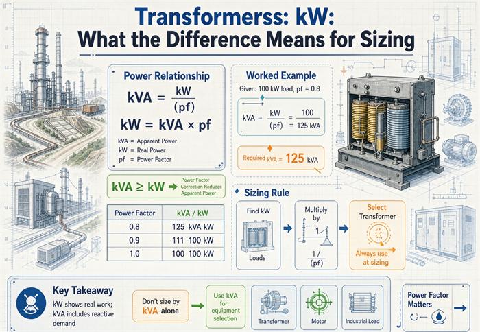
kVA is the current the transformer has to carry, kW is the work the load actually does, and the gap between them decides the order. The same 800 kW of load can need a 1,000 kVA unit or a 1,500 kVA unit. Four different kVA numbers settle that, and only one of them is printed on the nameplate.
Most explanations stop at kW = kVA × power factor. That equation is correct and it is also not enough to buy anything. It tells you how to convert a number. It does not tell you which number, measured where, on what day.
This article is about the second part, and it is written for someone holding a load list and an RFQ rather than a textbook. If you already know the power triangle, skip to the section on the size ladder. That is where the money is.
The short answer, and the part it leaves out
kVA is apparent power: volts times amps, at the terminals, no matter what the current is doing. kW is real power: the component of that product that actually turns a shaft, heats a tank, or lights a room.
Transformers are rated in kVA because their limit is thermal. Winding temperature rises with current squared, and current is set by kVA, not by kW. A transformer connected to a load at 0.70 power factor carries the same heat per kVA as one at 1.00, while delivering 30 percent less useful work. If you rated transformers in kW, the plate would be a lie the moment the load changed.
That is the textbook answer, and it is complete as physics. Where it fails as procurement advice is this: it implies a single power factor exists for your facility. It does not. Power factor is different at every load, different at every hour, and different at every point in the distribution system. Sizing on one number for all of that is where orders go wrong.
Four kVA numbers, and only one is on the nameplate
Here is the frame that makes the rest of this article make sense. When someone says “kVA” in a sizing conversation, they mean one of four things, and the four are rarely equal.
| Number | What it is | Where it comes from |
|---|---|---|
| Load kVA | What the equipment draws at its terminals | Load list, motor tables, measured data |
| Nameplate kVA | A thermal rating at a stated ambient and temperature rise | The transformer plate |
| Billed kVA | What the meter recorded and the tariff charged | Utility interval data |
| Usable kVA | What is left after harmonics, ambient, and voltage deviation | Nobody publishes this. You calculate it |
Load kVA is what you have to serve. Nameplate kVA is what you can buy. Billed kVA is what you pay for, and it is not the same quantity as either of the first two. Usable kVA is the number that determines whether the unit you bought will actually carry the load in August.
Reading a plate properly takes more than finding the biggest number on it, because the kVA field has conditions attached. Our guide to the nameplate fields walks them in the order a reviewer checks them.
A 1,000 kVA transformer at a site with 35 percent current distortion, a 50 °C ambient, and a supply sitting at the low end of the utility voltage range is not a 1,000 kVA transformer. It is closer to 700 kVA of real capability. That gap never appears on a quote.
What the difference costs you on the size ladder
Start with the number that changes the order. Take a fixed 800 kW of real load and vary only the power factor.
| Power factor | Required kVA | Line current at 480 V | Standard rung you must buy |
|---|---|---|---|
| 1.00 | 800.0 | 962 A | 1,000 kVA |
| 0.95 | 842.1 | 1,013 A | 1,000 kVA |
| 0.90 | 888.9 | 1,069 A | 1,000 kVA |
| 0.855 | 935.7 | 1,125 A | 1,000 kVA |
| 0.80 | 1,000.0 | 1,203 A | 1,000 kVA, at its limit |
| 0.70 | 1,142.9 | 1,375 A | 1,500 kVA |
Same kilowatts. Same building. Same production line. The only variable is how much reactive current the loads pull, and the answer moves from a 1,000 kVA unit to a 1,500 kVA unit, with the feeder, the breaker, and the fault current following it up.
Now run it the other way. You own a 1,000 kVA transformer. How much work can it do?
| Power factor | Usable kW | What it feels like |
|---|---|---|
| 1.00 | 1,000 | Electric resistance heat, incandescent lighting |
| 0.95 | 950 | Well corrected plant with modern motors |
| 0.90 | 900 | Typical mixed commercial |
| 0.855 | 855 | Motors plus some drives, uncorrected |
| 0.80 | 800 | Older motor-heavy plant |
| 0.70 | 700 | Welding, induction heating, lightly loaded motors |
A 43 percent spread in delivered work from one machine. If your facility runs at 0.70 and you assumed 0.90 when you bought, you are paying for a transformer that carries 900 kW and getting 700.
Where kW goes wrong: three nameplates
The instruction “add up the kW of everything that runs at once” is where most sizing errors enter. It hides three separate traps, and each one has a different fix.
A motor nameplate is shaft output, not input
A 100 HP motor delivers 100 HP at the shaft. That is 74.6 kW of mechanical work. The electrical input is higher, because the motor has losses, and the apparent power is higher again, because it magnetizes its own windings.
At NEMA Premium efficiency for a 100 HP four-pole machine, about 95.4 percent under the levels in 10 CFR 431 subpart B, the input is 78.2 kW. At 0.88 power factor, that is 88.8 kVA, or 107 A at 480 V three-phase.
If you take 74.6 kW and divide by 0.88, you get 84.7 kVA. You are 4.8 percent short before you have bought anything. On a motor-heavy plant with two hundred units, that 4.8 percent is the difference between fitting on your bus and not.
Now the more useful point. Do not run that calculation at all.
NEC Table 430.250 lists 124 A for a 100 HP motor at 460 V. That is 98.8 kVA, which is 11 percent above the 88.8 kVA you just calculated. The table already contains typical efficiency, typical power factor, and a margin on top. And 430.24 requires you to use it for feeder and branch calculations. So the code answer and the conservative answer are the same number, and it is not the one you get from the physics.
The habit to build: for motors, read the table. For everything else, convert with a stated power factor and write the power factor down next to the number. A load list where every line has both a kW and a PF is a load list you can defend. A load list with one kW total and one assumed PF is a guess with a spreadsheet around it.
A packaged chiller’s kW is rated at conditions you don’t have
A chiller, a compressor, or an air handler carries a nameplate kW that means full-load input at a specified rating condition. Your condition is different. At 95 °F ambient instead of 80, the compressor runs harder. At part load, the controls unload it and the kW drops, but the power factor drops faster.
The same thing happens on a plant bus with a hundred motors on it, which is why a rolling mill and a metallurgy site cannot be sized from a connected-load total alone.
That last part matters more than most people realize. A 100 HP motor at full load runs near 0.88 power factor. At a quarter of its shaft load, typical power factor falls to about 0.70, and efficiency drops too. Run the numbers:
| Shaft load | Input kW | Power factor | kVA drawn | Share of full-load kVA |
|---|---|---|---|---|
| 100% | 78.2 | 0.88 | 88.8 | 100% |
| 75% | 58.9 | 0.86 | 68.5 | 77% |
| 50% | 39.7 | 0.82 | 48.4 | 54% |
| 25% | 20.7 | 0.70 | 29.6 | 33% |
At a quarter of its mechanical output, the motor still pulls a third of its full-load kVA. So sizing a transformer to the average kW and calling it done is wrong in both directions: it undersizes the kVA, because the power factor at average load is worse than at rated load, and it oversizes nothing, because the peaks still land where they land.
Rule of thumb worth keeping: size the transformer on peak kVA, not average kW, and check what the power factor is at the load you actually run.
The meter reads an average, not a maximum
Utility demand is a maximum average over a short window, usually 15 or 30 minutes. Instantaneous peaks above that get flattened by the averaging. Startup inrush, which lasts seconds, barely registers.
That cuts both ways. It means a motor start does not usually set your demand charge. It also means a slow ramp that holds for fifteen minutes, like a chiller bank or a bank of chargers coming online together, sets it completely. Two facilities with identical kWh can have very different billed demand, and the difference is scheduling, not equipment.
Adding kVA: the warning is pointed at the wrong mistake
Every guide says do not add kVA arithmetically. That advice is correct in principle and misdirected in practice, because the error it warns about is small and safe, while the error people actually make is larger and dangerous.
Take a real mixed load: 540 kW of motor and process load at 0.95 power factor, plus 360 kW of welding and induction heating at 0.70.
Load A:  540 kW at 0.95  ->  568.4 kVA,  177.5 kVAR
Load B:  360 kW at 0.70  ->  514.3 kVA,  367.3 kVAR
Total:   900 kW,            544.8 kVAR

Arithmetic sum:   568.4 + 514.3      = 1,082.7 kVA
Vector sum:       sqrt(900^2 + 544.8^2) = 1,052.0 kVA
Blended PF 0.92:  900 / 0.92         =   978.3 kVA
True combined power factor: 900 / 1,052.0 = 0.856
Read the three results side by side.
Arithmetic addition overstates by 2.9 percent. It is wrong, and it is wrong in the safe direction. You would order 1,500 kVA either way, because 1,082 and 1,052 both exceed 1,000.
A single blended power factor understates by 7.0 percent. It produces 978 kVA, which rounds to a 1,000 kVA unit, which will be overloaded on the first cold morning when everything starts together.
That is the punchline. The method every article warns you off is off by 2.9 percent and conservative. The method nearly everyone uses, because it is the one line formula that fits on a slide, is off by 7.0 percent and puts you one rung short.
The correct approach is the third line of the code block: convert each load to kW and kVAR, add each separately, then recombine. It is one extra column in the spreadsheet and it eliminates the whole class of error.
kVA_total = sqrt((sum of kW)^2 + (sum of kVAR)^2), then PF = sum of kW / kVA_total. Never average the power factors. Averaging 0.95 and 0.70 gives 0.825, and the true answer here is 0.856, which is already enough to change a decision.
Power factor is not a constant
Worth stating plainly, because it is the assumption underneath every shortcut above: power factor is a property of an operating point, not of a machine.
The same motor has a different power factor at every load, as the table in the previous section shows. A plant has a different power factor at 2 a.m. than at 2 p.m., because the load mix changes. And a facility has a different power factor at the service than at a motor terminal, because the cables, the transformers, and the capacitor banks in between all contribute reactive power of their own.
This is why measured data beats calculated data every time for an existing facility. NEC 220.87 allows you to use twelve months of maximum demand data, increased by 25 percent, for exactly this reason. Twelve months of interval data contains every coincidence your plant is capable of. Your load list contains the ones you remembered.
For a new facility you have no choice but to calculate. When you do, put the power factor source next to every line. If it came from a motor table, say so. If it came from a nameplate, say so. If it is an assumption, mark it as one, because the reviewer will ask and the answer needs to already be on the page.
Displacement power factor and true power factor
Here is where modern plants get stuck, and where almost nothing written for buyers covers it.
The cos φ in kW = kVA × PF is displacement power factor. It accounts for the phase shift between voltage and current at the fundamental frequency. Capacitors fix displacement power factor. That is all they fix.
When the load is non-linear, which means drives, rectifiers, LED drivers, servers, and anything with a switch-mode supply, the current waveform is not a sine wave. That distortion adds current that carries no real power. Your meter sees the extra current. The result is that true power factor is lower than displacement power factor:
PF_true = PF_displacement x 1 / sqrt(1 + THD^2)Run it at a few distortion levels, assuming you have corrected displacement power factor all the way to unity with capacitors:
| Current THD | Distortion factor | True PF at DPF 1.00 | True PF at DPF 0.95 |
|---|---|---|---|
| 10% | 0.995 | 0.995 | 0.945 |
| 20% | 0.981 | 0.981 | 0.932 |
| 30% | 0.958 | 0.958 | 0.910 |
| 35% | 0.944 | 0.944 | 0.897 |
| 40% | 0.928 | 0.928 | 0.882 |
| 50% | 0.894 | 0.894 | 0.850 |
A six-pulse drive at full load typically runs 35 percent current THD. That caps your true power factor at 0.944 no matter how much capacitance you bolt on. A plant that is half drives by load can push THD past 50 percent, and then the ceiling is 0.894, which is below the 0.90 threshold most tariffs use.
This is a real and common failure. A facility installs a capacitor bank to fix a power factor penalty, the displacement meter reads 0.99, and the penalty does not go away, because the utility bills on true power factor and the true number is 0.90. The fix is not more capacitors. It is harmonic mitigation at the drives, or a detuned bank, and the two cost very different amounts.
Ask your utility one question before you buy anything: is the power factor on my bill displacement or true? The answer changes the equipment list.
For the transformer itself, distortion has a second effect that is purely thermal. Harmonic currents cause additional eddy current loss in the windings and the core, so a transformer feeding drives runs hotter than its kVA suggests. That is what K-factor ratings exist for, and it is why a standard unit serving a drives-heavy bus is effectively smaller than its plate.
What the utility actually bills
Two facilities can draw the same 400 kW and pay very different demand charges, because some tariffs bill kW and some bill kVA. If yours bills kVA, the power factor conversation stops being a technical detail and becomes a line item.
Take 400 kW at 0.855 power factor. That is 468 kVA.
| Demand rate | Billed on 400 kW | Billed on 468 kVA | Annual difference |
|---|---|---|---|
| $15 per kW-month | $6,000/mo | $7,020/mo | $12,240 |
| $24 per kW-month | $9,600/mo | $11,232/mo | $19,584 |
| $35 per kW-month | $14,000/mo | $16,380/mo | $28,560 |
A 2026 primary-service industrial tariff in Michigan, as one concrete example, carried roughly $24 per kW-month all in across its capacity, non-capacity, and distribution components, with a power factor penalty below 85 percent and an eleven-month ratchet set at 65 percent of the highest summer on-peak demand. Those three features together are why power factor work pays back in months at some sites and never at others.
The ratchet, and why one afternoon lasts a year
The ratchet deserves its own paragraph, because it is the part facility managers underestimate. On a ratcheted tariff, one bad afternoon in July sets a floor you pay for eleven months, whether or not you ever hit it again. That is a scheduling problem, not a transformer problem, but it is the same conversation.
The practical implication for sizing is narrow but real. If your tariff ratchets, the number that matters is not your average demand and not your typical peak. It is the single highest fifteen minutes you are capable of producing, because that is the one you will be billed against. Sizing a transformer to the typical peak and assuming the odd spike is a billing matter gets the equipment right and the budget wrong.
kVA is a thermal rating, and it moves
The last thing that separates the two concepts: a nameplate kVA is not a property of the box. It is a rating at stated conditions, and when the conditions change, the rating changes.
Under IEEE C57.12.00, a distribution transformer’s rated capacity is stated at a rated voltage, rated frequency, and a specified temperature rise above a specified ambient. Strip any one of those and the number loses meaning. A unit rated 1,000 kVA at a 55 °C rise over 40 °C ambient is not a 1,000 kVA unit at 50 °C ambient. It is a smaller one, and the derating is the same arithmetic that applies on a mine site or a rooftop.
Cooling class changes the number on the same core
Cooling class changes the rating on the same core and the same windings. An ONAN unit that adds fans becomes ONAF and gains capacity, because forced air removes more heat from the same surface. That is not marketing. It is the same thermal limit measured under different cooling. If you buy the ONAF rating and run the fans on a failed control circuit, you own the ONAN rating.
The federal efficiency floors work the same way, and this trips people up. Under 10 CFR 431.196, liquid-immersed units are tested at 50 percent load and low-voltage dry-type units at 35 percent, so the compliance point is not full load and not the operating point most plants actually run. A cast resin unit that meets the floor at 35 percent load is not automatically the more efficient choice at 80 percent, and the two are compared on different test points, which makes the labels incommensurable.
The voltage band moves it the other way
Voltage does the same thing in a different direction. A transformer is current-limited, so at a supply of 456 V, the low end of the ANSI C84.1 Range A service band, a 1,000 kVA unit rated at 480 V can deliver about 950 kVA at the same current. At 90 percent of nominal, 432 V, you are at 900 kVA. Utilities do not guarantee the top of the band, so a design that only works at exactly 480 V is a design that works on paper.
Worked example: 900 kW of mixed load
Put the whole chain together on the load from earlier.
Step one, separate kW from kVAR. 540 kW at 0.95 gives 177.5 kVAR. 360 kW at 0.70 gives 367.3 kVAR. Totals are 900 kW and 544.8 kVAR.
Step two, recombine. sqrt(900^2 + 544.8^2) is 1,052.0 kVA at a combined power factor of 0.856. The line current at 480 V is 1,265 A.
Step three, pick the rung. 1,052 kVA exceeds 1,000, so the order is 1,500 kVA. Not because of a growth allowance, and not because of a safety margin you invented, but because the arithmetic does not fit the smaller unit. Where the two rungs sit and what each one costs to feed is covered in the S20 sizing guide for the 30 to 31,500 kVA range.
Step four, check whether you have to accept that. Correct the 360 kW section from 0.70 to 0.95 and the reactive load falls by 249 kVAR. Recombine: 900 kW against 295.8 kVAR gives 947.4 kVA at 0.950, or 1,139 A. That fits a 1,000 kVA unit with 52.6 kVA of headroom.
So the choice is not “1,000 or 1,500.” It is “1,500 kVA transformer, or a 1,000 kVA transformer plus about 250 kVAR of capacitors at the load.” Compare those two quotes properly and the capacitor bank usually wins on capital cost by a wide margin, and it keeps winning on demand charges every month afterward.
Three caveats, because this is where the argument gets oversold.
The capacitors have to go at the load, not at the service. Correcting at the main breaker fixes the bill but leaves the reactive current flowing through your own feeders and your own transformer, so you keep the losses and the heating.
If the 360 kW section is drives, capacitors alone will not get you to 0.95 true power factor, for the reason in the previous section. You need detuned banks or filtering, and the economics change. The extreme case is a furnace transformer, where the load power factor is far below anything on a normal plant bus and correction is part of the process design rather than a bolt-on.
And a capacitor bank is a resonance risk. It interacts with the transformer’s impedance, and if the resonant frequency lands near the fifth or seventh harmonic, the bank amplifies the distortion it was supposed to help with. That is a study, not a catalog order.
FAQ
What is the difference between kVA and kW?
kVA is apparent power, the product of voltage and current at the terminals. kW is real power, the portion that does useful work. The ratio between them is power factor, so kW equals kVA times PF. A 1,000 kVA transformer at 0.80 power factor delivers 800 kW of work while carrying 1,000 kVA of current, and the heat in the windings follows the current, not the work. That is why transformers are rated in kVA and loads are usually described in kW.
How do I convert kW to kVA for transformer sizing?
Divide kW by power factor, but only after you have separated the loads. Convert each load group to kW and kVAR, add the two columns separately, then recombine with kVA = sqrt(kW^2 + kVAR^2). Dividing a single kW total by one assumed power factor is the most common sizing error, and it typically undersizes by 5 to 7 percent. Averaging power factors across loads makes it worse, because power factor does not average.
Why are transformers rated in kVA instead of kW?
Because the limit is thermal and the heat comes from current. Winding temperature rise scales with current squared, and current is set by apparent power. A transformer feeding a 0.70 power factor load carries more current per kW delivered than one feeding a 1.00 load, so the same kW produces more heat. Rating in kW would require knowing the load’s power factor at the time of manufacture, which no one does.
Does a 1,000 kVA transformer deliver 1,000 kW?
Only at unity power factor, which means resistance heating or incandescent lighting and nothing else. At 0.90 it delivers 900 kW. At 0.80, 800 kW. At 0.70, 700 kW. The kVA rating does not change, because it describes the current and the heat, while the kW delivered depends entirely on the load you connect.
Should I add kVA values together or add kW and kVAR separately?
Add kW and kVAR separately. Adding kVA arithmetically overstates the total, though only by about 3 percent, so it is conservative. Adding kW and applying one blended power factor understates by 5 to 7 percent, which is the error that actually causes trouble, because it can land you one standard size below what the load requires. Arithmetic addition is the smaller sin of the two.
Can power factor correction reduce the transformer size I need?
Yes, and the arithmetic is direct. A 900 kW load at 0.856 power factor needs 1,052 kVA, which forces a 1,500 kVA unit. Correcting to 0.95 adds about 250 kVAR of capacitors and drops the requirement to 947 kVA, which fits a 1,000 kVA unit with headroom. Two conditions apply: the capacitors belong at the load, not at the service, and if the load is mostly drives, capacitors alone will not reach the target because distortion caps true power factor independently.
Is motor nameplate kW the same as the kW it draws?
No. A motor nameplate states shaft output. A 100 HP motor delivers 74.6 kW of mechanical work and draws more than that electrically, because of losses in the windings, the core, and the bearings. At 95.4 percent efficiency the input is 78.2 kW, and at 0.88 power factor that is 88.8 kVA. For code calculations, skip the arithmetic and use NEC Table 430.250, which already includes typical efficiency, power factor, and a margin.
Bottom line
kVA and kW are not two names for the same thing with a correction factor between them. They answer different questions. kW tells you what the plant produces. kVA tells you what the copper has to carry, and the copper is what you are buying.
Get the load side right first: separate kW from kVAR, add them separately, and check what the power factor is at the load you actually run rather than at rated conditions. Then decide whether to spend the money on a bigger transformer or on correcting the power factor that made it big. That comparison, not the conversion formula, is the sizing decision.
If you are working through a load list and the numbers land between two standard sizes, send it over. Working out which rung is real, and which one is an artifact of an averaged power factor, is the part worth doing before the purchase order goes out.
Free: Transformer Specification Checklist
The exact RFQ sheet our engineers use — send it and get a quoted proposal within 24h.
Download checklist