The 75°C column of Table 310.16 is correct and most charts built from it still get a job red-tagged, because table ampacity is not usable ampacity. At 14, 12 and 10 AWG the breaker cap takes 14 to 31 percent off the number, and on a transformer feeder the device sets the wire, not the load.
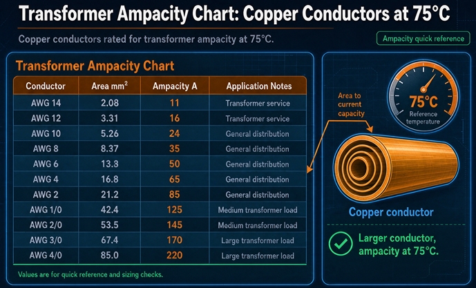
The chart, in one table
Here is the whole 75°C copper column, with the two extra columns that decide whether you can actually use it. Ampacity is from Table 310.16, three current-carrying conductors in a raceway, 30°C ambient. The last column is the ceiling that 240.4(D) puts on the overcurrent device for the three smallest sizes.
| Copper size | 60°C | 75°C | 90°C | Circular mils | 240.4(D) device cap |
|---|---|---|---|---|---|
| 14 AWG | 15 A | 20 A | 25 A | 4,110 | 15 A |
| 12 AWG | 20 A | 25 A | 30 A | 6,530 | 20 A |
| 10 AWG | 30 A | 35 A | 40 A | 10,380 | 30 A |
| 8 AWG | 40 A | 50 A | 55 A | 16,510 | none |
| 6 AWG | 55 A | 65 A | 75 A | 26,240 | none |
| 4 AWG | 70 A | 85 A | 95 A | 41,740 | none |
| 3 AWG | 85 A | 100 A | 115 A | 52,620 | none |
| 2 AWG | 95 A | 115 A | 130 A | 66,360 | none |
| 1 AWG | 110 A | 130 A | 145 A | 83,690 | none |
| 1/0 AWG | 125 A | 150 A | 170 A | 105,600 | none |
| 2/0 AWG | 145 A | 175 A | 195 A | 133,100 | none |
| 3/0 AWG | 165 A | 200 A | 225 A | 167,800 | none |
| 4/0 AWG | 195 A | 230 A | 260 A | 211,600 | none |
| 250 kcmil | 215 A | 255 A | 290 A | 250,000 | none |
| 300 kcmil | 240 A | 285 A | 320 A | 300,000 | none |
| 350 kcmil | 260 A | 310 A | 350 A | 350,000 | none |
| 400 kcmil | 280 A | 335 A | 380 A | 400,000 | none |
| 500 kcmil | 320 A | 380 A | 430 A | 500,000 | none |
| 600 kcmil | 350 A | 420 A | 475 A | 600,000 | none |
| 700 kcmil | 385 A | 460 A | 520 A | 700,000 | none |
| 750 kcmil | 400 A | 475 A | 535 A | 750,000 | none |
| 1000 kcmil | 455 A | 545 A | 615 A | 1,000,000 | none |
That is the table. Every ampacity chart on the first page of results reproduces some version of it, and almost all of them stop there.
Table ampacity is not usable ampacity
The number in the 75°C column answers one question: how much current can this conductor carry, continuously, without its insulation exceeding 75°C, in a 30°C ambient, with three current-carrying conductors in the raceway. It does not answer how much current you may put through it in a real circuit, because three other rules sit on top.
The first is the device. The second is the termination. The third is the ambient and the count. Any of them can take the number down, and none of them appear in the column.
The mistake that costs the most is assuming the column is the answer. A designer reads 4/0 at 230 A, specifies a 230 A feeder, and then discovers that the terminations are rated 75°C but the panelboard is rated 100 A, so the 60°C column applies and 4/0 is now a 195 A conductor. Or that the run goes through a mechanical room at 45°C and the 0.87 factor turns 230 into 200.
Start from the column. Then subtract.
The cap that makes the smallest three sizes lie
NEC 240.4(D) limits the overcurrent device protecting 14, 12 and 10 AWG copper to 15, 20 and 30 A, and it says so without regard to the ampacity column, without regard to the insulation rating, and without regard to the terminations.
| Size | 75°C ampacity | Maximum device | Shortfall | Max continuous load |
|---|---|---|---|---|
| 14 AWG | 20 A | 15 A | 25 percent less | 12.0 A |
| 12 AWG | 25 A | 20 A | 20 percent less | 16.0 A |
| 10 AWG | 35 A | 30 A | 14 percent less | 24.0 A |
| 8 AWG | 50 A | no cap | none | 40.0 A |
| 6 AWG | 65 A | no cap | none | 52.0 A |
The last column is the number people actually need, and it is the ampacity divided by 1.25, because a continuous load is 125 percent of itself by the time the device is chosen. Fourteen gauge carries 12 A continuously. Twelve gauge carries 16. Ten gauge carries 24.
Read the middle of that table again. Ten gauge has a table ampacity of 35 A and a device cap of 30 A, so its real continuous capacity is 24 A. That is 69 percent of the number printed in the column.
The rule exists for a reason that has nothing to do with the copper. Small conductors fail at their terminations, not in their insulation. A 10 AWG landing on a screw terminal at 35 A heats the lug, the screw creeps, the joint loosens, and the failure is a hot spot inside a panel rather than a conductor that quietly runs warm. The cap limits what the termination sees, which is why it applies regardless of how good the wire is.
There is one more consequence, and it is the most useful thing in this section. The cap distorts the value of the sizes.
| Size | Max continuous load | Circular mils | Continuous amps per kcmil |
|---|---|---|---|
| 14 AWG | 12.0 A | 4.11 | 2.92 |
| 12 AWG | 16.0 A | 6.53 | 2.45 |
| 10 AWG | 24.0 A | 10.38 | 2.31 |
| 8 AWG | 40.0 A | 16.51 | 2.42 |
| 6 AWG | 52.0 A | 26.24 | 1.98 |
| 4 AWG | 68.0 A | 41.74 | 1.63 |
Ten gauge is worse per pound of copper than eight gauge, which is not true of any other adjacent pair on the chart. The cap does that. If you are buying 10 AWG for a 24 A continuous load you are paying for 35 A of copper and using 24, and the next size up gives you 40 A for 59 percent more copper, which is a better trade than the column suggests.
That is why 10 AWG shows up so often as a mistake in small distribution work. It is big enough to look adequate and it is the last size before the cap stops mattering.
The 100 amp cliff in 110.14(C)
The second rule that overrides the column is about terminations, and it has a step in it that catches people who know the rule exists.
Equipment rated 100 A or less, or marked for conductors 1 AWG and smaller, is assumed to have 60°C terminations unless it is marked otherwise. Equipment rated over 100 A, or marked for conductors larger than 1 AWG, is assumed to have 75°C terminations. The conductor’s ampacity is limited by the lowest temperature rating anywhere in the circuit, and that includes the lug at each end.
The practical effect at the boundary is two wire sizes.
| Device rating | Column that applies | Smallest copper |
|---|---|---|
| 100 A, unmarked terminations | 60°C | 1 AWG, 110 A |
| 100 A, marked 75°C | 75°C | 3 AWG, 100 A |
| 110 A | 75°C | 2 AWG, 115 A |
A 100 A feeder wired in 3 AWG is correct if every termination in the run is marked 75°C. Wire it in 3 AWG against a panelboard with unmarked lugs and the inspector will ask for the marking, and if there is none, you are pulling 1 AWG. Two sizes, on one device rating, decided by a label inside a cover.
The reason this matters more on a transformer than on a panel feeder is that a transformer has terminations at both ends and they are often from different manufacturers. The primary lugs come with the transformer, the secondary lands in a panelboard somebody else bought, and the two do not always agree. Ask for the temperature marking on both before the wire is ordered, and put the answer on the drawing.
Ninety degree wire does not change any of this. THHN is rated 90°C in dry locations and you may use the 90°C column as the starting point for derating, but the final ampacity is still capped by the termination. Buying 90°C wire and landing it on a 75°C lug gives you a 75°C conductor with more expensive insulation.
Sizing a transformer feeder is a different question
A chart of conductor ampacity answers how much current a wire can carry. A transformer feeder asks a different question, which is what size wire this transformer requires, and the answer is set by the protection rather than by the load.
Two numbers drive it.
The first is 125 percent. Conductors feeding a continuous load must have ampacity of at least 125 percent of that load, and a transformer secondary serving a distribution panel is treated as continuous because nobody can demonstrate that it is not.
The second is the device. The overcurrent device on the primary of a transformer is sized at 125 percent of the primary full load current, rounded up to the next standard rating. The overcurrent device on the secondary is sized the same way against the secondary current. Once that device exists, the conductor has to be at least as big as the device, because 240.21(C)(2) says so for a secondary tap and because 240.4(C) says so above 800 A. Below 800 A on the primary side, 240.4(B) lets the conductor sit one standard step under the device, and that is the only relief anywhere in the chain.
Put those together and the wire is not sized to the load. It is sized to a device that was itself rounded up from the load.
Why the device, not the load, sets the wire
Take a 75 kVA transformer at 480 to 208Y/120. Secondary current is 208.2 A. Multiply by 1.25 and you need 260.2 A of conductor.
The chart says 300 kcmil carries 285 A, which clears 260.2. So a designer sizes 300 kcmil and feels finished.
Then the device. The secondary device is 125 percent of 208.2, which is 260.2, rounded up to the next standard rating, which is 300 A. Now 240.21(C)(2)(b) requires the secondary conductor ampacity to be not less than the rating of the device it supplies. Three hundred kcmil is 285 A. The device is 300 A. The conductor is 15 A short.
The answer is 350 kcmil at 310 A, one size up from what the load calculation asked for.
And there is no next-size-up relief here. The allowance in 240.4(B) that lets a conductor with a non-standard ampacity sit on the next higher standard device does not rescue a transformer secondary tap, because 240.21(C) states its own floor and that floor is the device rating. On a 300 A device the conductor is 300 A or larger, full stop.
That single step is the difference between a wire that fits a lug and a wire that does not, and it happens on the majority of the rows in the standard transformer ladder.
The device ladder, and why 260.2 becomes 300
The rounding is not uniform, and the non-uniformity decides which transformer sizes pay for it.
Standard device ratings are 15, 20, 25, 30, 35, 40, 45, 50, 60, 70, 80, 90, 100, 110, 125, 150, 175, 200, 225, 250, 300, 350, 400, 450, 500, 600, 700, 800, 1,000, 1,200, 1,600, 2,000, 2,500, 3,000, 4,000, 5,000 and 6,000 A.
There is no 900. There is no 1,400 and no 1,800. The ladder has gaps in it and those gaps are wider than they look, which is why a calculated 1,040.9 A becomes a 1,200 A device and a calculated 1,503.5 A becomes 1,600.
Now watch what that does to the primary of the standard line, where 125 percent lands just above a rung on some sizes and just below it on others.
| kVA at 480 V | 125 percent | Device chosen | Extra capacity bought |
|---|---|---|---|
| 45 | 67.7 A | 70 A | 3.4 percent |
| 75 | 112.8 A | 125 A | 10.8 percent |
| 112.5 | 169.1 A | 175 A | 3.5 percent |
| 150 | 225.5 A | 250 A | 10.9 percent |
| 225 | 338.3 A | 350 A | 3.5 percent |
| 300 | 451.1 A | 500 A | 10.8 percent |
| 500 | 751.8 A | 800 A | 6.4 percent |
The pattern alternates through the small sizes, and it has a consequence that shows up in bids. A 150 kVA and a 112.5 kVA differ by 33 percent in capacity, and the 150 forces a 250 A device where 225.5 A would have done. That one rung drags the conductor from 2/0 to 4/0, so a third more transformer buys a much larger feeder than a third more copper. The 75 kVA repeats the pattern against the 45.
None of this is an error in the code. It is what a discrete ladder does to a continuous calculation, and the only defense is to compute the device before you price the wire rather than after.
The 480 V primary table
Primary current is 1.2028 A per kVA. Multiply by 1.25 for the device, then choose the conductor. Where the device rounds up past the conductor’s ampacity and the device is 800 A or less, 240.4(B) permits the next size up, so the conductor can sit just under the device. Above 800 A it cannot.
| kVA at 480 V | Full load amps | 125 percent | Device | Copper, 75°C |
|---|---|---|---|---|
| 15 | 18.0 A | 22.6 A | 25 A | 10 AWG, 35 A |
| 30 | 36.1 A | 45.1 A | 50 A | 8 AWG, 50 A |
| 45 | 54.1 A | 67.7 A | 70 A | 4 AWG, 85 A |
| 75 | 90.2 A | 112.8 A | 125 A | 2 AWG, 115 A |
| 112.5 | 135.3 A | 169.1 A | 175 A | 2/0 AWG, 175 A |
| 150 | 180.4 A | 225.5 A | 250 A | 4/0 AWG, 230 A |
| 225 | 270.6 A | 338.3 A | 350 A | 500 kcmil, 380 A |
| 300 | 360.8 A | 451.1 A | 500 A | 700 kcmil, 460 A |
| 500 | 601.4 A | 751.8 A | 800 A | 2 sets of 500 kcmil, 760 A |
| 750 | 902.1 A | 1,127.6 A | 1,200 A | 3 sets of 600 kcmil, 1,260 A |
| 1000 | 1,202.8 A | 1,503.5 A | 1,600 A | 3 sets of 1,000 kcmil, 1,635 A |
The first row is the one that trips people up, and it has nothing to do with transformers.
A 15 kVA at 480 V draws 18.0 A. The device is 25 A. Twelve gauge copper carries 25 A in the 75°C column, so 12 AWG looks correct and is not, because 240.4(D) caps the device on 12 AWG at 20 A. You cannot put a 25 A breaker on 12 AWG. The conductor is 10 AWG.
That is a 15 kVA transformer, a device rated 25 A, and a wire size that two of the published tables get wrong because they read the column and stopped.
The 1,000 kVA row deserves a note. Three sets of 1,000 kcmil is 1,635 A, and it clears a 1,600 A device by 35 A. That is a real number and it is also the last time three sets per phase works, which is the ceiling that shows up in every conversation about 480 V distribution above 1,300 kVA.
The 208Y/120 secondary table
Secondary current is 2.7757 A per kVA, which is why the same kVA needs a much larger conductor at 208 V than at 480 V. Here the conductor must clear the device with no rounding relief, so the wire is often a size above the load calculation.
| kVA at 208Y/120 | Full load amps | 125 percent | Device | Copper, 75°C |
|---|---|---|---|---|
| 15 | 41.6 A | 52.0 A | 60 A | 6 AWG, 65 A |
| 30 | 83.3 A | 104.1 A | 110 A | 2 AWG, 115 A |
| 45 | 124.9 A | 156.1 A | 175 A | 2/0 AWG, 175 A |
| 75 | 208.2 A | 260.2 A | 300 A | 350 kcmil, 310 A |
| 112.5 | 312.3 A | 390.3 A | 400 A | 600 kcmil, 420 A |
| 150 | 416.4 A | 520.4 A | 600 A | 2 sets of 350 kcmil, 620 A |
| 225 | 624.5 A | 780.7 A | 800 A | 2 sets of 600 kcmil, 840 A |
| 300 | 832.7 A | 1,040.9 A | 1,200 A | 3 sets of 600 kcmil, 1,260 A |
| 500 | 1,387.9 A | 1,734.8 A | 2,000 A | 4 sets of 1,000 kcmil, 2,180 A |
Look at the last three rows and notice what happened. The conductor count stopped being a wire size and became a construction method. Four sets of 1,000 kcmil per phase is twelve 1,000 kcmil phase conductors plus a neutral in each set, in a transformer secondary, landing on a switchboard. Nobody pulls that. At that point the answer is busway, or a second transformer closer to the load.
The 45 kVA row is worth a second look because it lands exactly. 2/0 AWG carries 175 A and the device is 175 A. There is no margin and there is nothing wrong, and it is the last row in the table where the fit is exact rather than a size up.
The neutral, which sometimes counts
Every number above assumes three current-carrying conductors. A three-phase four-wire secondary has four, and whether the fourth counts changes the answer by a wire size.
The neutral of a four-wire wye circuit is not counted as a current-carrying conductor when it carries only the unbalanced current of linear loads, because in that case its current is below the phase current by construction. Add nonlinear load and the rule flips. Where the major portion of the load is nonlinear, the neutral is a current-carrying conductor, because triplen harmonics add in the neutral instead of cancelling.
Four counted conductors in a raceway takes the adjustment factor to 0.80. Run that against the table.
| kVA at 208Y/120 | Device | Linear load, three counted | Nonlinear load, conductor and amps after 0.80 |
|---|---|---|---|
| 45 | 175 A | 2/0 AWG, 175 A | 4/0 AWG, 184 A |
| 75 | 300 A | 350 kcmil, 310 A | 500 kcmil, 304 A |
| 112.5 | 400 A | 600 kcmil, 420 A | 1,000 kcmil, 436 A |
| 150 | 600 A | 2 × 350 kcmil, 620 A | 2 × 500 kcmil, 608 A |
On the 75 kVA, three-fifty kcmil carries 310 A and clears the 300 A device. Count the neutral and it carries 248 A, which does not. The fix is 500 kcmil at 304 A after the factor, two sizes up, on the most common small commercial transformer in North America.
The 112.5 kVA row is worse, and it shows why the single-conductor ceiling matters. Six hundred kcmil clears 400 A with room, but after the 0.80 it is 336 A and fails. Seven-fifty kcmil is 475 A before the factor and 380 A after, which also fails. The next single conductor that works is 1,000 kcmil at 545 A, and 545 times 0.80 is 436. One rule about the neutral moved a 600 kcmil feeder to 1,000 kcmil, and there is no size in between that helps.
The question that decides it is not “does this building have computers.” It is what fraction of the load is nonlinear at the panel the feeder serves. An office with LED lighting and switched-mode power supplies is nonlinear. A motor control center is not. A panel feeding a mix is a judgement call that should be written down, because the two answers differ by two wire sizes and by however much that copper costs.
There is a second reason to size the neutral generously, and it has nothing to do with ampacity. A full-size neutral is the default on a transformer because the winding is built that way, and downsizing it at the feeder while the transformer ships with a full-size X0 is a mismatch that shows up on the first harmonic survey.
Where one conductor stops working
A single copper conductor tops out at 1,000 kcmil and 545 A. Divide by 1.25 and the largest continuous load one run can serve is 436 A. Turn that back into transformer capacity and you get the ceiling for a single-conductor feeder at each voltage.
| Secondary voltage | Full load amps per kVA | Largest kVA on one conductor |
|---|---|---|
| 208 V | 2.7757 | 157 kVA |
| 240 V | 2.4056 | 181 kVA |
| 480 V | 1.2028 | 362 kVA |
| 600 V | 0.9623 | 453 kVA |
This is the least known number on the chart, and it decides more layouts than any ampacity value does.
At 208 V, a single conductor gets you to 157 kVA. A 150 kVA fits, with about 20 A of headroom in the conductor. A 225 kVA does not fit, and the design has to switch to two sets per phase. That is not a wire size decision, it is a decision about how many conduits leave the transformer, how big the pull is, and whether the secondary section has room for the lugs.
At 480 V the same ceiling arrives at 362 kVA, so a 300 kVA is a single run and a 500 kVA is not. Two sizes, one boundary, and it sits between two numbers that contractors quote interchangeably.
The ceiling exists because ampacity does not scale with copper. It scales with surface area, and surface area grows more slowly than cross section. Double the copper and you get about 1.4 times the amps, not two.
Same copper, two arrangements
Here is where the chart starts rewarding you for ignoring it.
The same copper carries more current when it is split into smaller conductors, and the effect is large enough to change a design rather than trim it.
| One conductor | Amps | Copper | Split version | Amps | Copper | Amps gained |
|---|---|---|---|---|---|---|
| 500 kcmil | 380 A | 500 kcmil | 2 × 250 kcmil | 510 A | 500 kcmil | +34 percent, same copper |
| 1,000 kcmil | 545 A | 1,000 kcmil | 2 × 500 kcmil | 760 A | 1,000 kcmil | +39 percent, same copper |
| 750 kcmil | 475 A | 750 kcmil | 2 × 350 kcmil | 620 A | 700 kcmil | +31 percent, 7 percent less copper |
| 1,000 kcmil | 545 A | 1,000 kcmil | 4 × 4/0 AWG | 920 A | 846 kcmil | +69 percent, 15 percent less copper |
The last row is the one worth staring at. Four runs of 4/0 carries 920 A on 846 kcmil of copper. One run of 1,000 kcmil carries 545 A on 1,000 kcmil. The parallel arrangement uses 15 percent less copper and carries 69 percent more current.
That is not a trick of rounding. It is the geometry of heat transfer. A big round conductor has less surface per unit of cross section than a smaller one, so it cannot shed heat as efficiently, and the 75°C column reflects that. The chart is telling you that big single conductors are a bad deal, in the only unit that matters.
Parallel conductors are not free, and the rule that governs them is in Article 310.
- Each conductor must be 1/0 AWG or larger
- Same length, same material, same size, same insulation type
- Terminated the same way at both ends
- Run with the same routing, so the impedance matches
The 1/0 minimum is what stops the extreme version of this. You cannot make a 500 A feeder out of sixteen 10 AWG conductors, even though the copper would carry it, because the code wants each parallel path to be substantial enough to divide current predictably.
The other cost is labor, and it is real. Four runs means four conduits, four pulls, twelve terminations per end instead of three, and four sets of lugs in a section that has to be big enough to hold them. In most North American markets the material saving is large enough that paralleling wins above roughly 350 kcmil, and the tipping point moves with copper price and with how hard the pull is. Ask your contractor for both arrangements before assuming the single run is cheaper, because on a long pull it usually is not.
The curve behind it, and the two sizes to avoid
The amps per unit of copper, computed across the range where it matters.
| Size | 75°C ampacity | kcmil | Amps per kcmil |
|---|---|---|---|
| 3/0 AWG | 200 A | 167.8 | 1.19 |
| 4/0 AWG | 230 A | 211.6 | 1.09 |
| 250 kcmil | 255 A | 250 | 1.02 |
| 300 kcmil | 285 A | 300 | 0.95 |
| 350 kcmil | 310 A | 350 | 0.89 |
| 500 kcmil | 380 A | 500 | 0.76 |
| 600 kcmil | 420 A | 600 | 0.70 |
| 750 kcmil | 475 A | 750 | 0.63 |
| 1,000 kcmil | 545 A | 1,000 | 0.55 |
The curve falls by half between 3/0 and 1,000 kcmil, and that is the entire argument for paralleling in one line.
It also identifies two sizes that are almost never the right purchase.
Seven hundred and fifty kcmil buys 15 A over 700 kcmil. Fifteen amps for 50,000 additional circular mils is three amps per 10 kcmil, against six and a half for the step from 4/0 to 250. If your calculation lands on 475 A and you have room for two conduits, two sets of 350 kcmil gives you 620 A on less copper. If you do not have room for two conduits, 750 is what you buy and you pay for it.
The other is 700 kcmil, for the opposite reason. It carries 460 A, which is 15 A more than 600 and 15 A less than 750, so it sits in a 30 A window that two neighbouring sizes already cover. A design that lands at 460 A is usually better served by moving the device or the load than by specifying a size that nothing else in the run was chosen around. Check the lug range before you order a size that sits alone on the ladder.
Derating, and the 4/0 that becomes a 160 amp conductor
The 75°C column assumes 30°C ambient and three current-carrying conductors. Move either assumption and the number moves, and the two multiply.
Take 4/0 copper at 230 A, a common secondary feeder size, and put it in a mechanical room.
| Condition | Factor | 4/0 ampacity |
|---|---|---|
| 30°C, three conductors | none | 230 A |
| 45°C ambient, three conductors | 0.87 | 200 A |
| 30°C, six conductors in one raceway | 0.80 | 184 A |
| 45°C, six conductors in one raceway | both | 160 A |
Six current-carrying conductors means two three-phase circuits sharing a raceway, which is exactly what happens when somebody decides to save a conduit on a dual-fed transformer.
At 160 A, that 4/0 is no longer a 175 A feeder. To hold 175 A through both corrections you need 251 A of table ampacity, which is 250 kcmil, one size up from where the design started.
The correction factors are in 310.15(B) for ambient and 310.15(C) for conductor count, and the counts are worth memorizing because they are not intuitive. Four to six conductors is 0.80, seven to nine is 0.70, ten to twenty is 0.50. A transformer feeding a panel with a spare conduit that later gets used for a second circuit moves from no derating to 0.80 without anybody changing the load.
One more adder that catches rooftop and outdoor work. Conductors within a few inches of a rooftop surface take an ambient adder on top of the outdoor design temperature, roughly 33°C at half an inch and tapering to nothing at three and a half inches. A 40°C rooftop becomes a 73°C design ambient, and the 75°C factor at that temperature is severe. A transformer on a roof with its secondary in conduit strapped to the deck is the classic case, and the conductor is often two sizes above what the load calculation produces.
The check nobody runs, and why it passes
There is a third conductor check that engineers worry about and rarely perform, which is whether the conductor survives the fault current long enough for the device to clear.
The arithmetic uses the adiabatic heating relation, and a published ICEA figure gives a usable anchor: 3 AWG copper, with 75°C insulation and a 250°C damage limit, withstands about 21,579 A for one cycle. Per circular mil that is 0.410 A, and the withstand scales with area and with the inverse square root of time.
| Conductor | Withstand, 1 cycle | Withstand, 6 cycles |
|---|---|---|
| 350 kcmil | 143,500 A | 58,600 A |
| 500 kcmil | 205,000 A | 83,700 A |
| 600 kcmil | 246,000 A | 100,400 A |
| 1,000 kcmil | 410,000 A | 167,400 A |
Now put the actual fault current beside it. Secondary fault current is the full load current divided by the per unit impedance, and at 5.75 percent that is a factor of 17.4.
| Transformer | Secondary fault current | Conductor in the table | Withstand at 6 cycles |
|---|---|---|---|
| 75 kVA at 208 V | 3,621 A | 350 kcmil | 58,600 A |
| 150 kVA at 208 V | 7,242 A | 2 × 350 kcmil | 117,200 A |
| 300 kVA at 208 V | 14,482 A | 3 × 600 kcmil | 301,200 A |
| 1,000 kVA at 480 V | 20,918 A | 3 × 1,000 kcmil | 502,200 A |
Every row has an order of magnitude of margin, and the margin grows with size because withstand scales with area while fault current scales with kVA and the two nearly cancel.
The honest conclusion is that conductor withstand is almost never the governing check on a distribution transformer secondary below a few megavolt amperes. The conductor is not the weak point. The lugs are, and so is the bracing that holds the bus still when 20,000 A tries to move it, and so is the short-circuit current rating of the equipment the conductor lands in, which is a separate number that has nothing to do with wire size.
That is worth saying because the check gets used as an excuse to upsize. When somebody proposes going two sizes up “for fault current,” the right question is which component is actually undersized, and the answer is usually the equipment rating rather than the conductor.
Voltage drop, where the chart stops mattering
Ampacity is a thermal limit and voltage drop is an electrical one, and on transformer feeders the thermal limit usually governs. Usually is not always.
Four hundred amps over 250 feet, at 480 V, in three sizes.
| Conductor | Resistance at 75°C | Drop at 250 ft | Percent of 480 V |
|---|---|---|---|
| 250 kcmil | 0.0515 ohms per 1,000 ft | 8.9 V | 1.86 percent |
| 500 kcmil | 0.0258 ohms per 1,000 ft | 4.5 V | 0.93 percent |
| 1,000 kcmil | 0.0129 ohms per 1,000 ft | 2.2 V | 0.47 percent |
At 480 V, even 250 kcmil stays under two percent over 250 feet, well inside the three percent feeder guideline. The chart governs and voltage drop is a footnote.
Now run the same conductor and current at 208 V. The volts dropped are identical, because the current and the resistance did not change. Eight point nine volts is 4.28 percent of 208 instead of 1.86 percent of 480, and it is now over the guideline before any margin.
That is the whole trap. A design that was fine on the 480 V primary becomes a voltage drop problem on the 208 V secondary using the same wire, and the reason is arithmetic rather than anything about the conductor. Low voltage secondaries are where voltage drop earns its keep, and long runs at 208 V are where a conductor sized purely from the ampacity column comes up short.
The rule of thumb is that voltage drop governs on runs over about 150 feet at 208 V, and rarely governs at all at 480 V under 300 feet. Check it rather than trusting the rule, because a 208 V run of 400 feet at high load will surprise you.
Copper against aluminum at 75°C
Aluminum is roughly two AWG sizes larger than copper for the same ampacity, and the ampacity ratio runs about 0.78 to 0.82 across the range.
| Copper | Amps | Aluminum | Amps |
|---|---|---|---|
| 2 AWG | 115 A | 1/0 AWG | 120 A |
| 1/0 AWG | 150 A | 3/0 AWG | 155 A |
| 3/0 AWG | 200 A | 250 kcmil | 205 A |
| 4/0 AWG | 230 A | 300 kcmil | 230 A |
| 350 kcmil | 310 A | 500 kcmil | 310 A |
| 500 kcmil | 380 A | 750 kcmil | 385 A |
Two things follow.
Aluminum needs about a third more circular mils for the same amps, and it is lighter per circular mil by a factor of three, so the same ampacity arrives at roughly 40 percent of the weight. On a long overhead run, or a big pull where weight is the problem, that is decisive. On a short feeder inside a building the weight does not matter and the trade comes down to material against termination risk.
The termination risk is the part people underestimate. Aluminum creeps under thermal cycling, so every termination needs the correct torque, a proper connector listed for aluminum, and in many cases an antioxidant. A copper feeder terminated badly gets hot. An aluminum feeder terminated badly gets hot, oxidizes, gets hotter, and eventually opens. The failure mode is worse, which is why some plants standardize on copper for anything inside a switchboard and accept aluminum only on the utility side.
Whatever you choose, the 75°C column has both materials and they are different columns. Reading copper ampacity for an aluminum conductor is a mistake that gets made because most charts print only one of them.
Two temperatures that are not the same temperature
A transformer nameplate says 150°C rise and 220°C insulation class. The ampacity chart says 75°C. Buyers read those two numbers together and conclude that something is inconsistent, or worse, that the wire is the weak link and the transformer has margin to spare.
They are unrelated numbers about unrelated objects.
The 75°C in the column is the temperature the conductor’s insulation is permitted to reach. It is a property of the wire, established by its listing, and it has nothing to do with what the wire is connected to.
The 150°C rise on the nameplate is how much hotter the winding is allowed to get above the surrounding air. Add the 40°C ambient and the winding can sit at 190°C, inside a 220°C insulation system. That is a property of the transformer, and it has nothing to do with the wire either.
The two meet in exactly one place, which is the terminal compartment. A dry-type transformer running at its rated rise has a case that is hot to the touch and a lug block that sits in air warmer than the room. That is why a transformer in a tight closet is a harder ambient than the same transformer in an open room, and why the correction factor in the derating section is not a formality on transformer work.
The other thing the two numbers do not do is trade against each other. A transformer with a 220°C insulation system does not permit 90°C terminations, and a conductor rated 90°C does not permit the transformer to run hotter. Each component is limited by its own rating, and the circuit is limited by the lowest one in it, which is almost always the termination at 75°C.
Small single-phase units, where the cap actually binds
The cap in 240.4(D) matters most on small transformers, because that is where the conductor sizes are small enough to be capped. A 480 to 240 volt single-phase unit is the common case.
| kVA | Secondary amps | 125 percent | Device | Copper, 75°C |
|---|---|---|---|---|
| 1 | 4.2 A | 5.2 A | 6 A | 14 AWG, capped at 15 A |
| 3 | 12.5 A | 15.6 A | 20 A | 12 AWG, capped at 20 A |
| 5 | 20.8 A | 26.0 A | 30 A | 10 AWG, capped at 30 A |
| 7.5 | 31.3 A | 39.1 A | 40 A | 8 AWG, 50 A |
| 10 | 41.7 A | 52.1 A | 60 A | 6 AWG, 65 A |
| 15 | 62.5 A | 78.1 A | 80 A | 4 AWG, 85 A |
The 3 kVA row is the one that catches people. Twelve and a half amps looks like 14 AWG work, and the 75°C column agrees at 20 A. But the 125 percent rule produces a 20 A device, and 240.4(D) caps the device on 14 AWG at 15 A. The conductor is 12 AWG.
The 5 kVA row is the boundary case in the other direction. Ten gauge carries 35 A in the column, the device is 30 A, and the cap is exactly 30 A, so it passes with nothing to spare. One size down in transformer and the cap decides the wire. Above 7.5 kVA the cap stops applying and the column governs again.
That is the shape of the whole rule. Below about 7.5 kVA the cap is the design constraint. From there to roughly 150 kVA the device and the 125 percent rule are the constraint, and that is the range where most commercial work sits. Above 150 kVA the conductor count takes over, because no single conductor reaches that far. The column is never the constraint on its own, at any size.
Three rows that get copied and are short
There is a table circulating that matches full load amps to conductor size directly, skipping the 125 percent, and three of its rows are wrong by enough to matter. Reading it against the 75°C column:
| Transformer | Full load amps | Published conductor | Its ampacity | 125 percent needs | Short by |
|---|---|---|---|---|---|
| 45 kVA at 208Y/120 | 124.9 A | 1/0 AWG | 150 A | 156.1 A | 6.1 A |
| 75 kVA at 208Y/120 | 208.2 A | 4/0 AWG | 230 A | 260.2 A | 30.2 A |
| 112.5 kVA at 208Y/120 | 312.3 A | 400 kcmil | 335 A | 390.4 A | 55.4 A |
The pattern is consistent and it is the reason the error survives. Each row picks the first conductor with ampacity above the full load current and stops there, so the 25 percent is never applied at all. The shortfall is whatever the gap happens to be between 1.25 times full load and the next conductor above full load, and across these three rows it runs from 6 A to 55 A. The last one is a wire size.
The legal answers are 2/0, 350 kcmil and 600 kcmil, and the first one is only correct because 175 A happens to be both the device rating and the ampacity of 2/0. On the other two the conductor is a full size above what the published table says.
The 75 kVA row is the one to remember, because 75 kVA 480 to 208Y/120 is the most common small commercial transformer in North America. It has a 300 A secondary device and it needs 350 kcmil, and a 4/0 secondary on a 300 A device is common enough in the field to be worth checking for by name. Those installations usually work, because the load sits well under the transformer rating, which is exactly why nobody finds out.
What to put on the RFQ
Conductor sizes are usually decided by the installing contractor, and the information that decides them is usually missing from the purchase order.
| Field | What to write | Why it matters |
|---|---|---|
| Primary and secondary voltage, connection | 480 V delta to 208Y/120 V, 4 wire | Sets the current at both ends |
| kVA | 75, or the next standard size | Sets the current, and the device |
| Impedance | 5.75 percent, with tolerance | Sets fault current and the withstand the wire needs |
| Termination temperature | 75°C marked, stated on both ends | Decides which column applies |
| Lug range | Accepts 350 kcmil per phase | A lug that stops at 4/0 changes the design |
| Neutral | Full size or 200 percent | Affects count in the raceway and derating |
| Ambient at the location | 40°C, or the actual room temperature | The correction factor nobody applies |
| Raceway scheme | One conduit per set, or bundled | The difference between 230 A and 184 A |
| Secondary protection | At the transformer or at the panel | Decides whether 240.21(C) applies |
| Conductor material | Copper or aluminum, stated | Different columns, different lugs |
| Short circuit withstand | Available fault current at the secondary terminals | The conductor has to survive until the device clears |
Two of those lines are worth arguing about before the order goes out.
The lug range is the one that turns into a change order. A transformer that ships with lugs accepting two 4/0 per phase cannot take the 350 kcmil that a 300 A secondary device requires, and the fix is a lug kit or a different transformer. Ask for the lug range in the submittal, in kcmil, and compare it to the conductor the calculation produces.
The ambient line is the one nobody asks about. A transformer in a dedicated electrical room sits near 30°C and the column applies as printed. The same transformer in a mechanical room with a boiler sits at 45°C and every conductor on it loses 13 percent. The transformer does not care, because it is rated for the ambient on its own nameplate. The wire does.
One example, all the way through
A 150 kVA, 480 delta to 208Y/120 wye, 5.75 percent impedance, feeding a distribution panel 200 feet away. Electrical room at 40°C. The panel serves office loads, so most of the load is nonlinear.
Step one, the secondary current. 416.4 A.
Step two, the device. 125 percent is 520.4 A. The ladder goes 500 then 600, so the device is 600 A. This is the first place the design leaves the calculation, because 520.4 would have been the number to design to and 600 is the number that exists.
Step three, the conductor from the chart. Six hundred amps needs two sets, because 1,000 kcmil tops out at 545 A. Two sets of 350 kcmil gives 620 A, which clears 600. On the chart alone, that is the answer, and it is 700,000 circular mils of copper per phase.
Step four, the neutral. Office load, so the neutral counts and each raceway has four current-carrying conductors. The factor is 0.80. Two sets of 350 now carry 496 A, which does not clear 600. Two sets of 500 carry 608 A and do.
Step five, the ambient. The room is 40°C, so the 75°C column takes 0.91 on top of the 0.80. Two sets of 500 now carry 553 A, which fails again. Two sets of 600 carry 611 A and clear.
The answer after five steps is two sets of 600 kcmil per phase, which is 1,200,000 circular mils against the 700,000 the chart produced. Seventy-one percent more copper, from two rules that are not on the chart.
Step six, voltage drop. Two sets of 600 have an effective resistance of 0.0107 ohms per 1,000 feet at 75°C. At 416.4 A over 200 feet the drop is 1.5 V, which is 0.74 percent of 208. Not a constraint here, and worth confirming rather than assuming.
Step seven, the primary. 180.4 A, 125 percent is 225.5 A, so the device is 250 A. 4/0 at 230 A clears 225.5 on paper, but at 40°C it is 209 A and no longer clears. The conductor is 250 kcmil at 232 A after correction, sitting under a 250 A device on the strength of 240.4(B).
Step eight, the lugs. Two sets of 600 per phase on the secondary, three conductors each, landing in a section that may have shipped with lugs for two 350s. This is the step that produces the change order, and it is the reason to ask for the lug range before the transformer is released.
The useful thing about this example is not the answer. It is that step three, the one the chart gives you, was wrong by a factor of 1.7 in copper, and every subsequent step made it worse rather than better.
The chart, read correctly
A 75°C ampacity table is a starting point and it is a good one. What it cannot do is tell you the wire size, because the wire size depends on four things the table does not contain: the temperature rating of the terminations, the rating of the device, the ambient where the raceway runs, and how many conductors share it.
If you are ordering a transformer and want the conductor sizes that go with it checked before the submittal goes out, start here and send the kVA, both voltages, the impedance, the ambient at the location, and the termination marking on the gear at each end. The useful answer needs the device rating too, because on a transformer secondary the device sets the wire and the load does not.
Here is the short version, in the order the numbers arrive.
- Read the 75°C column for the conductor you are considering, from a table with the circular mils in it, because the amps per kcmil is what tells you whether to split the run.
- Check the device. At 14, 12 and 10 AWG, 240.4(D) caps it at 15, 20 and 30 A, and that cap rather than the column decides the maximum continuous load.
- Check the terminations. Equipment at 100 A or less defaults to the 60°C column unless it is marked, which is two sizes at the boundary.
- Multiply the transformer current by 1.25, round up to a standard device, and then size the conductor to the device. On a secondary tap there is no next-size-up allowance, so the conductor meets the device or it does not.
- Apply the ambient and the conductor count, multiply the two factors, and see whether the size you chose still clears.
- Check voltage drop if the run is over 150 feet at 208 V. Below that at 480 V it is almost never the constraint.
- If the answer is above 350 kcmil, price the parallel arrangement before you accept the single run. The same copper in smaller conductors carries 34 to 69 percent more current.
Most of the failures in this area are not calculation failures. They are one of the seven steps being skipped, and the step that gets skipped is usually the second or the fourth, because both of them make the wire bigger and neither of them appears on the chart.
The chart is correct. It is just answering a narrower question than the one being asked of it.
FAQ
What is the ampacity of 4/0 copper at 75°C?
230 amps, in the 75°C column, with three current-carrying conductors in a raceway at 30°C ambient. That is the table value and it is not the size you order. A 4/0 on a transformer secondary has to clear the secondary device, so at 230 A it serves a 225 A device and nothing larger. Above that you move to 250 kcmil at 255 A, and then to 300 kcmil at 285 A.
Why does the table say 25 amps for 12 AWG when the breaker is limited to 20?
Because 240.4(D) caps the overcurrent device at 20 A for 12 AWG copper regardless of the ampacity column, the insulation rating or the terminations. The 25 A figure is the conductor’s thermal limit, not its permitted protection. With a 20 A device the maximum continuous load is 16 A, which is 20 divided by 1.25.
What size wire do I need for a 75 kVA transformer at 208Y/120?
350 kcmil copper at 75°C, which carries 310 A. The secondary current is 208.2 A, the 125 percent rule requires 260.2 A, and the device rounds up to 300 A. Because 240.21(C)(2) requires the conductor to be at least the device rating, 300 kcmil at 285 A is short and 4/0 at 230 A is far short.
Can I use the 90°C column if I install 90°C wire?
Only as a starting point for derating. The final ampacity is capped by the lowest temperature rating of any termination in the circuit, and most lugs, breakers and panelboards are marked 75°C. Insulation rated 90°C landed on a 75°C lug gives you a 75°C conductor, so the 90°C column buys nothing at the connection.
What size conductor feeds the primary of a 15 kVA transformer at 480 V?
10 AWG, even though 12 AWG carries 25 A in the 75°C column and the device is 25 A. The primary current is 18.0 A, 125 percent is 22.6 A, and the device rounds to 25 A. NEC 240.4(D) caps the device on 12 AWG copper at 20 A, so a 25 A breaker on 12 AWG is a violation. Ten gauge is the minimum.
How many amps does 1,000 kcmil copper carry at 75°C?
545 amps, which is the top of the 75°C copper column. Divide by 1.25 and the largest continuous load one run can serve is 436 A. Turned back into transformer capacity that is 157 kVA at 208 V and 362 kVA at 480 V, and those two numbers are where a single-conductor feeder stops being possible.
Can I use two 250 kcmil instead of one 500 kcmil?
Yes, and you should consider it. Two 250 kcmil conductors carry 510 A on the same 500,000 circular mils that one 500 kcmil uses to carry 380 A, which is 34 percent more current for the same copper. The trade is two conduits, twice the lugs and twice the terminations, so it wins on material and loses on labor.
What is the smallest conductor the code allows in parallel?
1/0 AWG. Article 310 requires each parallel conductor to be 1/0 or larger, the same length, the same material, the same size and the same insulation, terminated the same way at both ends. The minimum stops you from building a large feeder out of many small conductors that would divide current unpredictably.
How much ampacity do I lose at 45°C ambient?
Thirteen percent. The correction factor for the 75°C column at 45°C ambient is 0.87, so 4/0 copper drops from 230 A to 200 A. Add six current-carrying conductors in one raceway at 0.80 and the same conductor is 160 A, which no longer protects a 175 A feeder. The two factors multiply.
Is aluminum always two sizes larger than copper?
Roughly, and the ratio runs 0.78 to 0.82 across the range. So aluminum sits about two AWG sizes above copper for the same current, which is why 3/0 copper can be replaced by 250 kcmil aluminum and 4/0 by 300. Reading a copper ampacity for an aluminum conductor is the common mistake.
What size wire carries 400 amps continuously?
500 amps of ampacity, because 400 A of continuous load is 500 A by the 125 percent rule. One 1,000 kcmil carries 545 A. Two 250 kcmil carry 510 A on half the copper. Three 2/0 carry 525 A on 40 percent of the copper, and that is usually the cheapest legal answer, subject to conduit fill and termination room.
Does voltage drop ever control a transformer feeder?
At 208 V it often does. Four hundred amps over 250 feet drops 8.9 V in 250 kcmil, which is 1.86 percent of 480 V and 4.28 percent of 208 V. The volts dropped are the same, so the smaller the system voltage the more a long run matters. At 480 V, voltage drop rarely controls below 300 feet.
Free: Transformer Specification Checklist
The exact RFQ sheet our engineers use — send it and get a quoted proposal within 24h.
Download checklist