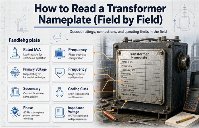
Read a transformer nameplate in four zones: identity across the top, ratings in the middle left, performance data to its right, and physical weights along the bottom edge. Four fields decide whether the unit fits your job, and they are kVA, the high and low voltage pair, percent impedance, and the cooling code. Three quick arithmetic checks catch everything else.
Here is the honest split with our other nameplate page. That one, how to read a transformer nameplate and technical parameters, works through what each rating means and how the parameters hang together. This one is the field version. It walks the physical plate from the top left corner to the bottom right, tells you which numbers sit where, and shows the checks that catch a mis-stamped plate before the crane shows up.
Most guides sort fields by importance. That’s logical, but it doesn’t help when you’re standing in front of a 4 foot by 2 foot steel plate with forty stamped lines and a flashlight in your teeth. Plates are laid out by convention, not by urgency. Learn the convention and you can read any plate in ninety seconds, including one from a factory you’ve never bought from.
The 90-second version. Zone 1 gives you the serial number and the standard. Zone 2 gives you kVA, voltages, taps and frequency. Zone 3 gives you %Z, temperature rise, cooling, vector group and losses. Zone 4 gives you mass, oil and sound. If the four numbers in Zone 2 and Zone 3 don’t survive the three arithmetic checks, stop reading and call the supplier.
The four zones and what each one settles
Every liquid-filled distribution plate I’ve seen, whether it came from Ohio, Shanghai, or Chennai, follows roughly the same geography. Dry-type plates compress the same information into a smaller label with different symbols.
| Zone | Where it sits on the plate | Fields you’ll find | Decision it settles |
|---|---|---|---|
| 1 Identity | Top band, above the ratings | Manufacturer, serial number, month and year of build, standard mark | Warranty, spare parts, test report retrieval |
| 2 Ratings | Middle left, largest type on the plate | kVA (often dual), HV and LV voltage, tap table, phase, frequency, rated currents | Will it physically fit the system |
| 3 Performance | Middle right, or a boxed sub-table | %Z, no-load and load loss, temperature rise, cooling code, vector group, insulation level, sound level | Will it behave under load and under fault |
| 4 Physical | Bottom band | Total mass, untanking mass, oil mass and volume, fluid type, connection diagram | Can you move it, set it, and contain a spill |
The layout matters because it tells you what the manufacturer thought was primary. On North American plates the kVA and voltage block is almost always the largest type, because that’s the number the utility and the inspector check first. On export plates built to IEC 60076, the vector group sometimes gets equal billing with the kVA, because in Europe and Asia the connection decides whether the unit can join an existing bus.
Zone 1: who built it, when, and to what rulebook
Start here even though nothing in this zone affects sizing. You start here because every later question routes through it.
The serial number is the only key that opens the factory file
Write it down first. Not the kVA, not the voltage. The serial number.
That string is what the manufacturer uses to pull the design record, the routine test report, the loss measurement sheet, and the bill of material. If a bushing cracks in year nine, the serial number gets you the correct part on the first try instead of the third. If a warranty claim turns into an argument, the serial number is the argument.
Photograph it separately and zoomed in. Serial numbers are usually stamped in a small font near the top edge where paint pools and corrosion starts.
The year of build tells you how much insulation life is already spent
Plates show month and year, sometimes just the year. A 1996 unit and a 2021 unit can carry identical kVA and voltage, and they are not the same asset.
Kraft paper insulation ages on a clock that runs faster when the unit runs hot. A liquid-filled unit that spent twenty-five years at moderate load is somewhere past the middle of its useful life. One that spent the same years at 90 percent load in a Texas pump house is closer to the end. The plate can’t tell you which one you have. It can tell you which question to ask.
The standard mark narrows the test regime
Look for one of these:
- IEEE C57.12.00 for liquid-immersed distribution and power transformers, the general requirements document
- IEEE C57.12.01 for dry-type general requirements, covering cast-coil and resin-encapsulated units
- IEC 60076-1 for the international power transformer family
- UL 1561 for dry-type units rated 600 V and below
- UL 1562 for dry-type units from 601 V to 35,000 V
Why this matters for a buyer: two plates can show the same 1000 kVA at 5.75 percent impedance and still not be interchangeable documents. Temperature rise test methods, loss reference temperatures, and insulation level definitions differ between the IEEE and IEC families. A replacement unit built to the other family will pass its own tests and still leave your engineer unable to compare the two reports line by line.
If you’re buying across that boundary, read IEC 60076 vs ANSI/IEEE standards for export transformers before you approve the drawing. The efficiency paperwork is where the two systems diverge most, and in the U.S. the loss figures on the plate have to reconcile with the tables in 10 CFR 431 subpart K.
Zone 2: the rating block, where slashes and brackets do real work
This is the block people photograph and send to suppliers. It’s also the block people misread most often, because the notation is a compressed shorthand that nobody ever explains out loud.
kVA, and the two-number plate
A single number is simple. 1000 kVA means 1000 kVA.
Two numbers mean something else. A plate reading 1000/1250 kVA, ONAN/ONAF is one transformer with two ratings, and the second one only exists while the fans are running.
- 1000 kVA is the self-cooled rating. Oil circulates by convection, air moves by convection, no fans, no pumps. This rating holds with the auxiliary power off.
- 1250 kVA is the forced-air rating. Fans push air across the radiators. Lose the fan supply, lose the rating.
Some plates carry three numbers, something like 1000/1250/1400 kVA under ONAN/ONAF/OFAF. Same logic, three cooling stages, three capacities. The jump from self-cooled to forced-air typically lands between 25 and 33 percent, and the jump to forced-oil forced-air adds a bit more.
Here’s the part that bites. Design your load to the first number, not the second. The 1250 kVA figure is headroom for a hot week, not a capacity you should plan around, because every hour you spend above the self-cooled rating depends on a fan motor, a control circuit, and a filter that nobody has cleaned since commissioning.
If you want the full letter-by-letter treatment of cooling codes, that lives in transformer cooling classes explained: ONAN, ONAF, AN, AF. Here we only need enough to read the slash.
The voltage line and its three punctuation marks
This is where most misreads happen, and it’s purely a notation problem. Three patterns cover almost everything you’ll see in North America.
Pattern 1: a slash between two voltages. 480Y/277 V or 12470GY/7200 V.
The slash separates line-to-line voltage from line-to-neutral voltage. It only appears when the winding is wye-connected and the neutral is brought out. The ratio between the two numbers is always 1.732, because that’s what the square root of three does.
- 480 divided by 277 is 1.732
- 12,470 divided by 7,200 is 1.732
- 208 divided by 120 is 1.733
If you see a slash and the ratio isn’t about 1.732, either the plate is wrong or you’re reading two different fields that got printed next to each other.
The Y means wye. The GY means grounded wye, neutral solidly grounded at the source. A delta winding never carries a slash, because there’s no neutral to reference. So 480D is a valid plate. 480/277D is not, and if you find one, someone made a mistake.
Pattern 2: a bracket after the primary voltage. 10(20) kV or 13.8(13.2) kV.
Brackets indicate a dual-ratio winding, meaning the unit can run on either primary voltage by changing taps or links. Common on European distribution units during the 10 kV to 20 kV grid transition. Read it as “two valid primary voltages, one at a time.”
Pattern 3: a dash followed by a tap range. 13800-2×2.5% or 12470 ±2×2.5%.
Everything after the dash is tap data, not a second voltage. The 2×2.5% means two steps up and two steps down at 2.5 percent each, which gives five positions total. Some plates print ±2×2.5%, some print 2-2.5%, some just print the voltage table and skip the shorthand.
The tap table is a voltage list, not a percentage
This is the single most useful thing on the plate that almost nobody reads.
Good plates print five rows, one per tap position, each with its own primary voltage. A 12,470 V unit with ±2×2.5% looks like this:
| Tap position | Primary voltage printed | What it’s for | Secondary at 12,470 V incoming |
|---|---|---|---|
| 1 (+5%) | 13,094 V | Feeder runs 5% high | 457 V |
| 2 (+2.5%) | 12,782 V | Feeder runs 2.5% high | 468 V |
| 3 (nominal) | 12,470 V | Nominal | 480 V |
| 4 (−2.5%) | 12,158 V | Feeder runs 2.5% low | 492 V |
| 5 (−5%) | 11,847 V | Feeder runs 5% low | 505 V |
Look at the right column. When you move the tap to a higher primary voltage, the secondary goes down. This is backwards from what most people assume on their first read, and it causes a specific, repeatable field failure.
The reason is turns. Tapping up adds primary turns. More primary turns for the same primary voltage means fewer volts per turn, so the secondary produces less. It’s not a control setting, it’s a winding ratio.
So the practical rule: the tap position number is the primary voltage that position is designed to accept, not the voltage it delivers.
If your incoming feeder sits at 12,900 V and you leave the tap at nominal, your secondary sits at about 497 V, and every 460 V motor on that bus runs 3.5 percent over nameplate. You fix that by moving to tap 1. If instead you reason “the voltage is high, so I need a higher tap to push it up,” you’ve just made it worse by another 5 percent.
This is also why “my secondary voltage is low” is the most common service call in the business, and why the answer is so often a tap left in the wrong position after a maintenance outage. A crew pulls the unit, tests it, puts it back, and sets the tap wherever it was in the shop. Nobody checks against the feeder.
Check the tap position against the printed table before every energization after service. Photograph the tap pointer, not just the plate.
Phase, frequency, and the currents you may have to derive
Phase shows as 1-Ph or 3-Ph, sometimes as 1φ or 3φ. Frequency shows as 60 Hz or 50 Hz. Neither is negotiable. A 50 Hz unit on a 60 Hz system runs at higher flux density and higher core loss, and the temperature rise printed on the plate no longer describes what’s happening inside.
Rated currents are usually printed next to each voltage. When they’re missing, derive them. The arithmetic is one line and it’s also check number one later in this article.
For three-phase: amps = kVA × 1000 ÷ (1.732 × line-to-line volts).
- 500 kVA at 480 V gives 601 A
- 750 kVA at 480 V gives 902 A
- 1000 kVA at 480 V gives 1,203 A
- 1500 kVA at 480 V gives 1,804 A
For single-phase: amps = kVA × 1000 ÷ volts. A 50 kVA unit at 240 V gives 208 A.
Zone 3: the performance block, where the expensive surprises live
Zone 2 tells you whether the unit fits the system. Zone 3 tells you whether it behaves once it’s on the system. This is the block a price-only comparison skips.
Percent impedance, and the kVA base it sits on
Percent impedance, printed as %Z or uk, is the share of rated voltage you’d apply to one winding to push full-load current through the other winding while it’s shorted. Lower value means the transformer holds voltage better under load and lets more fault current through. Higher value means the opposite.
You probably already know that. What you may not know is that the number has a base, and the base is usually printed right next to it in small type.
On a dual-rated 1000/1250 kVA unit, the impedance is normally stated on the self-cooled 1000 kVA base. That’s the conservative choice by the manufacturer, and it’s the right one, but it creates a calculation trap.
Fault current is full-load current divided by impedance as a decimal. Change the kVA base and the fault current changes, even though the impedance percentage doesn’t, because the winding is the same winding and impedance is a property of the winding geometry, not of the cooling.
- At 1000 kVA on a 5.75 percent unit: 1,203 A ÷ 0.0575 gives about 20.9 kA
- At 1250 kVA on the same unit, fans running: 1,503 A ÷ 0.0575 gives about 26.1 kA
That’s a 25 percent jump in available fault current with no change to a single digit on the plate. If your fault study assumed the self-cooled number while the plant runs with fans on all summer, your breakers are undersized by exactly the margin between those two figures.
The safe rule: run the fault study at the highest capacity the unit will actually operate at, not the lowest. Study the fans-on case. If the fans can run, they will run, usually on the hottest day of the year when everything else is already stressed.
Impedance is also stated at a reference temperature, usually the same 85 °C used for load loss. Small type again. If a quote gives you a bare percentage with no reference, ask.
Temperature rise, and the twenty-year decision hiding in two digits
Temperature rise is printed as 65 °C or 55 °C for liquid-filled units, and as 80 °C, 115 °C, or 150 °C for dry-type. It’s the allowable rise above ambient at rated load, not an absolute temperature.
Do the addition and the number gets real. At a 40 °C ambient, which is the standard reference maximum:
- 65 °C rise gives an average winding temperature of 105 °C
- 55 °C rise gives an average winding temperature of 95 °C
- Dry-type at 150 °C rise gives a winding temperature of 190 °C
Now apply the aging rule that insulation engineers use. For class A paper insulation, life halves for every 8 °C above the rated hot-spot temperature. That’s not a marketing rule of thumb, it’s the Montsinger relationship, and it’s why a 55 °C rise unit costs more and lasts longer.
A 10 °C difference between a 65 °C rise unit and a 55 °C rise unit maps to roughly a 2.4× difference in thermal life at the same load. Both plates say 1000 kVA. Only one of them is still healthy in year thirty.
This is also why a 65 °C rise unit installed in a room that runs at 47 °C in August is quietly running at 112 °C average winding temperature, which is 7 °C into the accelerated zone. The plate isn’t lying. The room is.
If the room can’t hold 40 °C, the nameplate number is not the number you’re operating at, and you should be asking for a derating table rather than a bigger unit.
The cooling code, letter by letter
Liquid-filled codes run four letters. The first pair describes the internal medium and its circulation, the second pair describes the external medium and its circulation.
| Code | Internal | Internal circulation | External | External circulation | Typical use |
|---|---|---|---|---|---|
| ONAN | Oil | Natural | Air | Natural | Standard distribution, no fans |
| ONAF | Oil | Natural | Air | Forced | Second rating stage, fans on radiators |
| OFAF | Oil | Forced (pumps) | Air | Forced | Large power units, high ambient |
| ODAF | Oil | Forced, directed | Air | Forced | Generator step-up, high loss density |
| KNAN | Less-flammable fluid | Natural | Air | Natural | Indoor units needing reduced clearances |
The K prefix is worth a second look. It means a fluid with a fire point above 300 °C, typically a natural ester like FR3 or a synthetic ester. For indoor installations this changes the code conversation, because less-flammable fluids generally allow smaller clearances and can reduce fire suppression requirements under the adopted building code.
Dry-type codes are shorter. AN is air natural, no fans. AF is air forced. Two letters, same logic, and the same caveat about the second rating depending on a fan.
What the code costs you in the room: fans add sound, usually 3 to 6 dB(A) over the self-cooled figure, and they add a maintenance item. A failed fan on an ONAF unit doesn’t trip anything. It just quietly drops you back to the ONAN rating while the load keeps climbing, and the first symptom is a temperature alarm three weeks later.
Vector group and the clock face
The vector group tells you two things at once: how the windings are connected, and how far the secondary is shifted in phase from the primary.
Dyn11 reads as: high-voltage winding in delta, low-voltage winding in wye with neutral brought out, phase shift of 11 on the clock.
The clock convention works like this. Put the high-voltage line-to-neutral phasor at 12 o’clock. The low-voltage phasor points at a number. Each hour is 30 degrees. So 11 o’clock means the secondary leads the primary by 30 degrees.
Dyn1 is also 30 degrees, but in the opposite direction. Yyn0 is zero shift, which is why it shows up on units that parallel with older wye-wye installations.
Two transformers will not parallel unless three things line up:
- Same vector group, including the clock number. Not “both are Dyn,” the same full code.
- Same turns ratio, within about 0.5 percent at the operating tap.
- Impedance within about 10 percent of each other, with a capacity ratio no wider than 3 to 1 for reasonable load sharing.
Break the first one and you don’t get poor sharing. You get a 30 degree phase difference between two secondaries tied to the same bus, which is a short circuit through the windings. The breakers see it as a fault and they’re right.
If you’re matching a new unit to an existing plant, the vector group on the old plate is a hard constraint, not a preference. photograph it and put it in the RFQ.
Insulation level: the LI and AC pair
Older and export plates print insulation level as a pair, something like LI 95 / AC 34. North American plates often print just a BIL number.
- LI is the lightning impulse withstand level, in kV peak. The unit survived a 1.2 by 50 microsecond wave at that value without breakdown.
- AC is the power-frequency withstand, in kV rms for one minute.
Typical values by class, for reference only. The plate always controls.
| Winding voltage class | Typical LI (kV peak) | Typical AC (kV rms) |
|---|---|---|
| 480 V or 600 V | 10 to 30 | 2.5 to 10 |
| 2.4 kV | 45 to 60 | 19 to 26 |
| 13.8 kV | 95 or 125 | 34 or 45 |
| 25 kV | 125 or 150 | 50 or 60 |
| 34.5 kV | 150 or 200 | 70 or 80 |
The buyer question isn’t “is this high enough.” It’s “does this match the exposure.” A unit inside a clean switchroom sees almost no surge. A pad-mounted unit at the end of a long rural feeder with overhead exposure sees a lot. Mismatch that and the arrester you installed is coordinated to the wrong clamp voltage.
Losses, and the reference temperature they hide
Two loss numbers appear on good plates: no-load loss and load loss, both in watts.
- No-load loss, sometimes called core loss or iron loss, is consumed continuously whenever the unit is energized, whether or not anything is connected. It comes from magnetizing the core.
- Load loss, sometimes called copper loss, scales with the square of the load current. It’s the I²R heating in the windings plus stray and eddy losses.
Load loss is always stated at a reference temperature, and that temperature is tied to the temperature rise class. A 65 °C rise unit is normally referenced to 85 °C. A 55 °C rise unit is normally referenced to 75 °C.
If you’re comparing two quotes and one gives load loss at 85 °C while the other quietly gives it at 75 °C, the second one looks better than it is. Correct it before you compare:
Pk at 75 °C = Pk at 85 °C × (234.5 + 75) ÷ (234.5 + 85)
That works out to about 0.969, or roughly 3 percent lower. Use 225 instead of 234.5 for aluminum windings. It’s a small correction, but on a 9,000 W load loss figure it’s 280 W of phantom savings that will follow you through a thirty-year cost model.
Once the numbers are on the same base, the two watt figures turn into a bill:
| Item | Value |
|---|---|
| No-load loss | 1,500 W |
| Load loss at rated | 9,000 W |
| Assumed average loading | 40% |
| Annual energy from losses | 25,754 kWh |
| Annual cost at $0.10/kWh | $2,575 |
| Thirty-year present value at 7% | $31,959 |
The discount factor for thirty years at 7 percent is 12.409. That single multiplier is why a $2,000 price difference between two units is almost never the deciding number, and why “we’ll look at losses later” is a decision to spend $30,000 later.
Load loss also has a second life. It’s the input to the impedance calculation and to the temperature rise, so a supplier who shaves loss numbers to win a bid is usually shaving something else too.
Sound level, and the distance it’s measured at
Sound shows as a dB(A) figure, and the figure is meaningless without a distance and a cooling state. A plate reading 64 dB(A) could mean 64 at one meter with fans off, or 64 at 0.3 meters with fans on. Those are not the same machine in a residential courtyard.
Typical NEMA average sound levels for liquid-filled distribution units, fans off:
| Rating | Typical dB(A) |
|---|---|
| 500 kVA | 60 |
| 750 kVA | 62 |
| 1000 kVA | 64 |
| 1500 kVA | 66 |
| 2000 kVA | 68 |
These are averages, not limits. If the site has a noise ordinance, ask for the guaranteed level, the measurement distance, and the standard it was measured to. Then ask what happens with fans running, because that number is usually 3 to 6 dB higher and it’s the number that shows up in a complaint.
Zone 4: mass, oil, and the crane you forgot to book
The bottom band looks like housekeeping. It’s the band that decides whether installation day goes well.
Three weights, three different jobs
Plates often print three mass figures, and they don’t substitute for each other.
- Total mass is the shipping and operating weight, oil included. This drives foundation design, shipping permits, and the size of the crane.
- Untanking mass is the weight of the core and coils assembly without the tank. This is what you lift when the unit needs a core inspection or a rewind. It’s usually 55 to 70 percent of total mass.
- Heaviest piece is the single heaviest component for rigging. Sometimes the tank with oil, sometimes the core and coils, depending on the design.
Book the crane against the right number. A crew that sizes the lift from untanking mass will be short by a few tons, and they’ll find out while the unit is in the air.
Oil volume, and the 1,320 gallon line
Oil appears as both mass and volume, because mass matters for transport and volume matters for spill containment.
Typical liquid volume for pad-mounted and small substation units:
| Rating | Typical oil volume | SPCC single-container trigger |
|---|---|---|
| 750 kVA | about 290 gal | Below 1,320 gal |
| 1000 kVA | 198 to 291 gal depending on design | Below 1,320 gal |
| 1500 kVA | about 500 gal | Below 1,320 gal |
| 2000 kVA | about 600 gal | Below 1,320 gal |
The 1,320 gallon figure is the SPCC threshold for a single container. Most distribution units sit well under it, which is why a single 1000 kVA pad-mount usually doesn’t trigger secondary containment on its own. But SPCC aggregates across the site. Three 1,500 kVA units in one yard put you at 1,500 gallons, and now the containment question is live.
Check the fluid type in the same field. Mineral oil is the O class. Natural ester is K. The fire point difference is the difference between a 300 °C fluid and a 360 °C fluid, and on an indoor installation that difference can change the required clearance to combustible construction. If the unit is liquid-filled, the oil-immersed transformer range shows how fluid choice and containment get specified together.
Connection diagram and terminal markings
Most plates carry a small schematic. Use it. Terminal markings follow convention, H1 H2 H3 on the high side and X1 X2 X3 on the low side for North American practice, U V W and u v w under IEC. The small n in Dyn11 means the neutral is brought out to a terminal, not that it’s grounded. Grounding is your job at installation, not the factory’s.
Conductor material shows as Cu or Al. Copper windings cost more and hold up better under harmonic load and short-circuit stress. Aluminum is lighter and cheaper. Both are legitimate. Just make sure the quote you approved and the plate you received agree, because that swap is one of the quietest ways to lose money on an import order.
Three arithmetic checks that catch a bad plate
Now the part that separates reading a plate from understanding one. Run three checks. Each takes under a minute. Together they catch most of the plates that shouldn’t be on your dock.
Check 1: does the printed current match the kVA and voltage?
Compute full-load current from the rating and compare it to the printed current. They should match within rounding.
| Rating | At 480 V | At 208 V | At 240 V |
|---|---|---|---|
| 500 kVA | 601 A | 1,388 A | 1,203 A |
| 750 kVA | 902 A | 2,082 A | 1,804 A |
| 1000 kVA | 1,203 A | 2,776 A | 2,406 A |
| 1500 kVA | 1,804 A | 4,164 A | 3,608 A |
I’ve seen supplier pages list a 1000 kVA transformer at 2,776 A. That’s the 208 V current, posted against a product family that ships as 480 V. The number isn’t invented. It’s the right answer to a different question, and it’s the kind of error that makes an engineer distrust a whole catalog.
When the printed current is off by a factor near 2.3, you’re looking at a 208 V versus 480 V mix-up. When it’s off by about 1.73, someone divided by the line voltage instead of the product of root three and the line voltage. When it’s off by 3, someone used single-phase math on a three-phase unit.
Check 2: does the voltage pair match the connection?
The slash and the connection have to agree. Three valid combinations and one impossible one.
| Printed as | Implied connection | Valid? |
|---|---|---|
| 480Y/277 V | Wye, neutral brought out | Yes |
| 12470GY/7200 V | Grounded wye, neutral brought out | Yes |
| 480 V (alone) | Delta, or wye without neutral | Yes |
| 480/277D | Claims a neutral on a delta winding | No |
The last row is nonsense, and if it shows up on a submittal drawing, it means someone copied a voltage field into a connection field. Catch it at the drawing stage, not at commissioning.
One more: check which winding is which. HV and LV mean high voltage and low voltage, not input and output. A transformer works in both directions within its insulation limits, but a unit with taps on the HV side gives you ratio adjustment only when the HV side is the one connected to the source. Install it backwards and your taps do nothing useful.
Check 3: is the impedance on the same kVA base you’re calculating with?
Covered above, but it deserves its own check because it’s the error that survives review. Take the %Z, take the kVA base it’s stated on, and confirm they match the kVA you’re using in the fault calculation.
On a dual-rated unit, if you take the 1250 kVA fault current and pair it with an impedance stated on 1000 kVA, you’re mixing bases. Do the whole calculation on one base and state the base in the study.
A 25 percent error in available fault current is the difference between staying inside a 22 kA switchboard rating and needing a 42 kA one. On a 1500 kVA unit at 480 V with 5.75 percent impedance, the fault current is about 31.4 kA, which is already above the 22 kA ceiling that standard distribution gear can hold. You can’t fix that with a bigger breaker. You fix it with a higher impedance unit, a 42 kA rated assembly, or splitting the load across two smaller units on separate buses.
What the plate does not tell you
A nameplate is a factory promise about a new unit. It is not a health report and it is not a system study. Six things matter to your installation and none of them are printed on the steel.
| Not on the plate | Why it matters | What to check instead |
|---|---|---|
| Harmonic content of the load | Extra eddy current loss in windings and stray loss in structural parts; a standard unit derates | Load study; specify a K-rated unit if non-linear load exceeds about 20% |
| Site altitude | Air cooling loses effectiveness above roughly 1,000 m; capacity drops | Site elevation; ask for the manufacturer’s altitude derating table |
| Room ambient above 40 °C | Every degree above the reference eats insulation life | Temperature logger in the actual room, summer data, not design intent |
| Overload history | Insulation ages on load, not on calendar | Loading records, dissolved gas analysis, oil test history |
| Winding condition today | A 1998 plate still reads 1000 kVA on a unit with a failing winding | Insulation resistance, turns ratio test, DGA, routine test results |
| Actual demand | Plate capacity is a ceiling, not a measurement | Thirty-day demand log from the meter, not the connected load schedule |
The gap between plate capacity and actual demand is where most oversizing lives. A plant that installed a 1500 kVA unit for a connected load of 1,400 kVA and actually peaks at 620 kVA is paying no-load loss on 900 kVA of capacity it will never use, every hour, for thirty years.
Reading a plate to order a replacement unit
This is where nameplate reading turns into money. A replacement order that starts with “we need a 1000 kVA transformer” will produce a unit that doesn’t fit, and the mistake surfaces at commissioning when the schedule has no slack.
The five fields that lock a replacement
| Field | Why it locks the order | What goes wrong if you skip it |
|---|---|---|
| kVA and cooling class together | 1000/1250 ONAF is not the same as 1250 ONAN | You buy a physically larger unit that doesn’t fit the pad |
| Both voltages, with the slash intact | 480Y/277 is not 480D | You lose the 277 V lighting neutral |
| Vector group, full code | Dyn11 is not Dyn1 | Circulating current at parallel, or a redesign of the whole bus |
| Percent impedance, with base | A 4 percent unit replacing a 5.75 percent unit raises fault current by 44% | Downstream gear exceeds its interrupting rating |
| Tap range and type | Off-circuit versus on-load is a different machine | You promised voltage regulation the unit can’t deliver |
Add two more if the unit parallels anything: the existing unit’s impedance and its tap position at the time of the study.
What to send with the RFQ
A photo of the plate plus a typed transcription of these fields gets you a usable quote on the first pass. Anything less gets you a sales reply asking questions.
REPLACEMENT TRANSFORMER REQUEST
Reference unit serial: __________  Year of build: ______
Standard on plate: IEEE C57.12.00 / IEC 60076-1 / other: ______

Rating:  ______ kVA at ______ (ONAN / ONAF / AN / AF)
HV:  ______ V,  taps: ______ ,  connection: ______
LV:  ______ V,  connection: ______ ,  neutral brought out: Y / N
Phase: ____   Frequency: ____ Hz

Impedance: ______ % on ______ kVA base at ______ °C
No-load loss: ______ W    Load loss: ______ W at ______ °C
Temperature rise: ______ °C (or K)    Insulation class: ______
Insulation level: LI ______ kV / AC ______ kV
Vector group: ______
Sound level: ______ dB(A) at ______ m, fans on/off

Total mass: ______    Untanking mass: ______    Oil volume: ______ gal
Fluid type: mineral oil / natural ester / silicone / dry-type
Enclosure: indoor / outdoor / pad-mounted    Ambient design: ______ °C
Altitude: ______ m    Expected loading profile: ______
Parallel operation with existing unit: Y / N  (attach that plate too)
That form is also the document you attach to the purchase order, which is how you avoid the argument in month four about whether the delivered unit matches what was quoted.
If you’re also deciding between construction types, oil-immersed vs dry-type transformer: how to choose covers the selection logic. The plate reading doesn’t change much, but the field set does.
Dry-type plates read differently
A dry-type plate carries maybe 60 percent of the information of a liquid-filled plate, in a different vocabulary. If you read it with the liquid-filled checklist in your head, you’ll think fields are missing. They aren’t. They’re just named differently.
| Liquid-filled field | Dry-type equivalent | Notes |
|---|---|---|
| Cooling code ONAN / ONAF | AN / AF | Two letters, same meaning: natural or forced air |
| Temperature rise 55/65 °C | Rise 80, 115, or 150 °C | Higher rise is normal; the insulation class is higher too |
| Insulation class A (105 °C) | Class F (155 °C) or H (180 °C) | Printed as the letter, sometimes as the temperature |
| Oil volume and fluid type | No oil field | Instead look for the environmental class |
| BIL | BIL, often lower for the same voltage class | Air is a weaker dielectric than oil |
| Not present | C1 / C2, E1 / E2, F1 | IEC 60076-11 climatic, environmental, fire classes |
| Not present | IP rating | Enclosure ingress protection, e.g. IP23 or IP54 |
| Not present | Winding material Cu / Al cast or wound | More prominent than on liquid units |
The C2 E2 F1 string is the one worth learning. C2 is the climatic class for operation down to −25 °C. E2 is the environmental class for condensation and humidity. F1 is the fire class, meaning limited flammability and low smoke. A dry-type unit installed outdoors or in a humid basement without E2 is a corrosion and tracking problem waiting for its first wet season.
For cast-resin units, the dry-type transformer product line listing shows how those class strings map onto actual build options.
How to photograph a plate so it’s still useful in five years
Every guide says take a photo. Almost nobody says how, and a bad photo is worse than no photo because it looks like evidence.
Take three.
- The wide shot. Full plate plus a recognizable piece of the unit, so future-you knows which transformer this was. Include the bay number or the stenciled asset tag if there is one.
- The straight-on shot. Plate filling the frame, camera parallel to the surface, no angle. Angled shots distort the tap table and make the small type unreadable. Use a light at a low angle from the side, because stamped characters read by shadow, not by brightness. A direct flash on a painted plate wipes out the stamping entirely.
- The detail shot. The serial number and the tap pointer, zoomed. These are the two fields you’ll need most and the two that corrode first.
Write the date and the unit’s location in the filename. 2026-10-30_bay4-tx2.jpg beats IMG_4471.jpg every time, and it survives a phone migration.
Take the photos on delivery day, before the unit goes into service, and again after any maintenance that involves the tap changer. Plates corrode, paint gets over-sprayed during touch-ups, and a legible photo has rescued a lot of urgent replacement orders.
Worked example: one plate, eight decisions
Here’s a plate read end to end. It’s a composite of common North American distribution values, not a specific unit.
What’s stamped:
- 1500 kVA, 3-phase, 60 Hz, ONAN
- HV 12470GY/7200 V, taps ±2×2.5%, delta primary
- LV 480Y/277 V
- Impedance 5.75% on 1500 kVA at 85 °C
- Temperature rise 65 °C, class A insulation
- Vector group Dyn1
- Insulation level LI 95 / AC 34 (HV), LI 10 / AC 2.5 (LV)
- No-load loss 2,100 W, load loss 14,800 W at 85 °C
- Total mass 12,400 lb, untanking mass 8,300 lb, oil 500 gal, mineral oil
- Sound 66 dB(A) at 1 m, fans off
Decision 1: does the capacity fit? 1500 kVA is a standard step on the ANSI ladder, so it’s a stockable design. At 480 V the full-load secondary current is about 1,804 A.
Decision 2: does the voltage pair work? 12,470 V grounded wye primary at 7,200 V to neutral, 480Y/277 V secondary. The earthing matches a solidly grounded utility source, and the 277 V neutral supports lighting circuits without a separate transformer.
Decision 3: what does the primary protection need? At 125 percent of primary full-load current, 69.4 A becomes 86.8 A, which lands on a 90 A standard device. Check the switchgear can host it.
Decision 4: what does the secondary protection need? 1,804 A at 125 percent is 2,255 A, so a 2,500 A frame. Per NEC 240.6(A) standard ratings, there’s nothing between 2,000 A and 2,500 A, so don’t plan on a 2,250 A device.
Decision 5: what fault current must the gear interrupt? 1,804 A divided by 0.0575 gives about 31.4 kA at the secondary terminals before any motor contribution. Standard 22 kA distribution gear can’t hold that. The options are a 42 kA rated assembly, two 750 kVA units on separate buses, or a higher impedance unit, and 8.2 percent impedance would be needed to bring the fault level under 22 kA. Standard distribution designs don’t go there.
Decision 6: which tap position? With the feeder running at nominal 12,470 V, tap 3 is correct and the secondary sits at 480 V. If the measured feeder sits at 12,900 V, tap 1 brings the secondary back to about 473 V. Leave it at tap 3 and every 460 V motor runs 3.5 percent high.
Decision 7: what does 65 °C rise cost in life? At 40 °C ambient, average winding temperature is 105 °C, right at the class A limit with a hot spot above it. If the room actually reaches 45 °C in summer, the unit is running about 5 °C into the accelerated aging zone all season.
Decision 8: what goes on the replacement RFQ? kVA and cooling together, both voltages with the slash, Dyn1 in full, 5.75 percent on the 1500 kVA base at 85 °C, and the tap range with type. Plus the 31.4 kA fault figure, because a supplier quoting a 4 percent impedance replacement would raise it to about 45 kA and quietly invalidate the switchgear.
That’s eight decisions from one plate, and seven of them came from numbers most buyers never copy down.
FAQ
What should I read first on a transformer nameplate? Start with the serial number and year in the top band, then move to the kVA and voltage block. The serial number is what the factory needs to pull the design record and test report. The kVA and voltages decide whether the unit fits your system at all. Read impedance and cooling third, and physical data last.
What does 1000/1250 kVA mean on a nameplate? It’s one transformer with two ratings. 1000 kVA is the self-cooled rating with fans off. 1250 kVA is available only while the forced-air fans are running. Design your load to the first number, because the second one depends on fan power, a control circuit, and clean radiators.
What does the slash mean in 480Y/277 V? The slash separates line-to-line voltage from line-to-neutral voltage. 480 V is phase to phase, 277 V is phase to neutral, and the ratio is 1.732. A slash only appears on a wye winding with the neutral brought out. A delta winding never carries one.
How do I check whether a nameplate is internally consistent? Run three checks. Multiply kVA by 1,000, divide by 1.732 times the line voltage, and compare with the printed current. Confirm the voltage pair matches the stated connection, since a slash implies wye. Confirm the percent impedance is stated on the same kVA base you’re using for the fault calculation.
What does 65 °C rise mean on a nameplate? It’s the allowable winding temperature rise above ambient at rated load, not an absolute temperature. At a 40 °C ambient, 65 °C rise puts the average winding at 105 °C. Insulation life roughly halves for every 8 °C above the rated hot spot, so a 55 °C rise unit of the same kVA lasts substantially longer.
Why does the secondary voltage go down when I move to a higher tap? Because a higher tap position adds primary turns. More primary turns at the same primary voltage means fewer volts per turn, so the secondary output drops. The tap number printed on the plate is the primary voltage that position is designed to accept, not the voltage it delivers.
Why is load loss stated at a specific temperature? Winding resistance rises with temperature, so load loss has to be referenced to a stated value. A 65 °C rise unit normally uses 85 °C, and a 55 °C rise unit uses 75 °C. To convert from 85 °C to 75 °C, multiply by about 0.969 for copper windings. Comparing quotes without matching the reference overstates the lower-temperature unit.
What fields do I need to order a replacement transformer? Five lock the order: kVA together with the cooling class, both voltages with the slash intact, the full vector group including the clock number, percent impedance with its kVA base and reference temperature, and the tap range with its type. Add the existing unit’s impedance and tap position if the new unit will parallel with anything.
What is untanking mass on a transformer nameplate? It’s the weight of the core and coils assembly without the tank, usually 55 to 70 percent of total mass. It’s the figure you need for a core inspection or rewind, not for the shipping lift. Total mass drives the foundation and the crane; heaviest piece drives the rigging plan.
Does a nameplate tell me the transformer is in good condition? No. A nameplate is a factory promise about a new unit. It says nothing about harmonic loading, site altitude, room ambient, overload history, or the condition of the winding today. Those come from a load study, a temperature log, dissolved gas analysis, and routine electrical tests.
Free: Transformer Specification Checklist
The exact RFQ sheet our engineers use — send it and get a quoted proposal within 24h.
Download checklist