Core-type and shell-type are not really two competing designs. They are two size ranges wearing the same question. Core form covers roughly 250 kVA to 15,000 kVA at 138 kV and below, shell form takes over above that line, and under about 5 MVA you are usually buying a third thing that neither label describes. The choice is a lot narrower than the internet makes it sound.
That is the whole answer, and it took me a 1956 Westinghouse engineering paper to find it stated with numbers. Everything below is about what changes for you if you cross one of those lines, and how to write a spec that survives the crossing.
If your actual question is which cooling method or which insulation system to pick, those are separate axes and this page will not help. Start with the oil versus dry comparison and the cooling class guide, then come back when you know you want a liquid-filled unit and only the core construction is open.
The short answer, by size
Here is the decision laid out the way a purchase order actually gets written.
| Your rating | What the market will sell you | Where the decision sits |
|---|---|---|
| 10 to 500 kVA, distribution | Wound core (spirally wound, grain-oriented) in North America; stacked core form in IEC markets | Core construction is not a real choice, it is a factory standard |
| 500 kVA to 5,000 kVA | Stacked core form, three limbs, almost universally | Only the limb count is negotiable |
| 5,000 kVA to 15,000 kVA | Core form, three or five limbs | Limb count, transport height, and Z0 are the real decisions |
| Above 15,000 kVA, above 138 kV | Shell form becomes common, core form still available | This is where the two-design question is genuinely live |
| Furnace, rectifier, mobile, traction | Shell form or a shell-like special, even at modest kVA | Fault duty and envelope decide, not kVA |
The 15,000 kVA and 138 kV figures are not from a standard. They come from a Westinghouse paper published in November 1956, which put it plainly: above 15,000 kVA and above 138 kV, shell-form construction has the desirable features, and from 250 kVA through 15,000 kVA at 138 kV and below, experience had shown core form to be most suitable. That boundary is 70 years old and the industry has not really moved it. You can read the original scanned issue yourself.
So when a supplier’s blog tells you shell type is for “large power transformers and harsh conditions,” they are quoting that 1956 line without the numbers. Now you have the numbers.
What actually differs: one drawing, three consequences
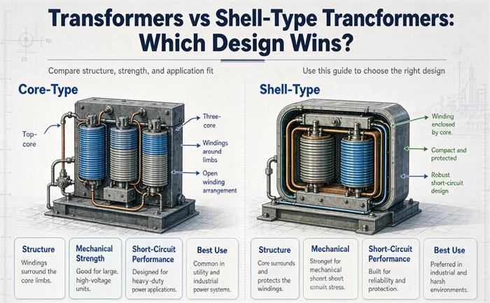
Every downstream difference traces back to one geometric fact. In core form, the winding wraps around a limb and the core is inside it. In shell form, the winding is a flat stack of pancakes and the core laminations sit on both flat faces of that stack, holding it like a bookend.
Everything else is downstream of that.
The flux path
Core form uses a single closed magnetic circuit per limb, with yokes top and bottom. Shell form splits the flux into two parallel paths that rejoin, which is why a three-phase shell-form unit is essentially three single-phase shell units standing side by side, sharing a tank.
That split path is shorter around the window, so the magnetizing path is shorter, which is the mechanical origin of the claim that shell form has lower no-load loss. It also means the core metal is in physical contact with the winding faces, which is the origin of the cooling problem.
The winding form
Core form: cylindrical concentric layers, one winding inside the other, wound on a mandrel and slid onto the limb. You can see the outside of the outer winding, and so can the oil.
Shell form: flat rectangular pancakes stacked in a sandwich, with the high and low voltage discs interleaved. Interleaving shortens the leakage path and improves impulse voltage distribution along the winding, which is why shell form shows up in lightning-heavy service.
The support structure
Core form windings are held against short-circuit force by external clamping frames, bands, and tie rods. The force is carried by hardware you bolt on.
Shell form windings are held by the core laminations themselves, pressing on both flat faces. The force is carried by the same steel that carries the flux.
That is the entire mechanical argument, and it is a good one. It just is not free.
The line nobody quotes: 250 kVA to 15,000 kVA
Ask a supplier for a shell-form 2,000 kVA distribution transformer and watch what happens. In North America you will get either a polite no or a quote for something they build once a year at a premium. In Europe and Asia you will usually get a core-form unit described as shell form, because the sales engineer is translating from a Chinese datasheet where 壳式 has a slightly different job.
This is the part the comparison articles never say: between about 250 kVA and 15,000 kVA, in the voltage class most industrial buyers live in, core form is not the winner, it is the only entry.
The reason is manufacturing economics, not electrical performance. Core form lets you wind coils on a mandrel, test them, then slide them on. Shell form requires you to build the winding and the core around each other, alternating, with the insulation and the clamping designed as one assembly. That is fine when you build six units a year at 200 MVA. It is painful when you build four hundred units a year at 1,000 kVA.
So if you are buying 1,000 kVA at 13.8 kV, the “which design wins” question resolves to: whatever your shortlist of factories builds, and your job is to make sure that thing meets your loss, impedance, and fault requirements. Naming a construction you cannot buy is how a specification turns into a four-week delay and a change order.
Where the question disappears entirely
Below roughly 5 MVA, and especially below 500 kVA, the honest answer is that you are often buying neither.
General Electric ran an advertisement in Electrical World in March 1950 announcing that Spirakore, their spirally wound core, had been extended “to the entire line of single-phase, outdoor distribution transformers, up through 500 kVA.” The claim in that ad was specific: the core was wound so the flux followed the grain direction of the cold-rolled steel, which let them build a smaller, lighter unit.
A wound core is not the stacked E-I lamination that every core-versus-shell article describes. It is a continuous strip of grain-oriented steel wound into a rectangular loop, then annealed and sometimes cut and re-clamped around a pre-wound coil. It is core form in the sense that the winding wraps around the core. It is not core form in the sense that anyone means when they write a comparison table.
Three things follow, and they matter at the dock:
- If a supplier sends you a comparison table and your rating is 300 kVA, the table is about a product nobody is quoting you.
- A wound core cannot be disassembled to replace a winding. A stacked core can. That is a repair decision, not an efficiency decision.
- Wound cores are quieter and have lower no-load loss for the same steel grade, which is why they won the distribution market and why amorphous ribbon, which is also wound, fits the same production line.
You can check this from the drawing in under a minute, and I will show you how further down.
Which one burns less power: the 47 percent answer
Both designs, at the same rating and the same steel grade, land within a few tenths of a percent of each other on full-load efficiency. That is why every article says “roughly similar” and stops.
Stopping there is a mistake, because the split between the two loss components is not the same, and only one of them runs 8,760 hours a year.
Take a representative 1,000 kVA pair. Core form: no-load loss 1,500 W, load loss 9,000 W. Shell form: a shorter magnetizing path takes no-load loss down about 13 percent to 1,300 W, and less copper in a sandwich winding pushes load loss up about 10 percent to 9,900 W. These two pairs are illustrative, not measured, and the point of what follows is that you should never accept a pair like this without the guarantee.
Set them equal and solve for the load factor:
core:   1,500 + 9,000 x^2
shell:  1,300 + 9,900 x^2

equal:    200 = 900 x^2
           x^2 = 0.222
             x = 0.471
47 percent. Above that average load factor, core form loses less energy. Below it, shell form does.
Run the energy bill at three operating points, at $0.10 per kWh over 30 years discounted at 7 percent (present value factor 12.409):
| Average load factor | Core form, annual energy | Shell form, annual energy | 30-year PV gap |
|---|---|---|---|
| 30% | 20,236 kWh ($2,024/yr) | 19,193 kWh ($1,919/yr) | shell ahead by $1,293 |
| 47% | 30,556 kWh | 30,545 kWh | tie |
| 60% | 41,522 kWh ($4,152/yr) | 42,609 kWh ($4,261/yr) | core ahead by $1,348 |
Look at the size of those differences next to the price of the transformer. They are a rounding error on a $30,000 unit. This is the honest finding: at distribution and medium power ratings, the loss argument does not decide anything. It only starts to matter past 10 MVA, where the watts scale with the kVA and the dollars scale with them.
Why the crossover moves
Two things shift that 47 percent line, and both are negotiable in a quote.
The first is steel grade. A better grain-oriented grade cuts no-load loss in both designs, but it cuts the shell-form number proportionally further, because shell form already had the shorter magnetizing path. Push the core-form no-load loss from 1,500 W down to 1,200 W and the crossover moves to 55 percent, which means core form now wins on a much wider range of duty.
The second is how you value the two loss components. Utilities do not weight a no-load watt and a load watt the same, because one runs 8,760 hours and the other does not. If your evaluation assigns a capitalised value per watt to each, run the comparison with your own weights rather than with a generic energy price. The crossover will move, and it will move in the direction your load profile actually runs.
What this does mean is that anyone selling you shell form on an efficiency claim is selling you a story. If they cannot hand you a guaranteed no-load and load loss pair in watts, at a stated reference temperature, they do not have the number they are claiming.
Ask for both values separately. Then check them against the efficiency table that applies to you, because DOE floors under 10 CFR 431.196 are keyed to kVA and BIL, not to construction. The regulation does not care which shape you buy. Both designs pass or fail on the same watts.
Short-circuit force is where shell form earns its place
Electromagnetic force on a winding goes with the square of current. This is the number that makes the geometry argument concrete.
| Fault current, times rated | Force on the winding, times rated-load force |
|---|---|
| 10x | 100x |
| 16x | 256x |
| 20x | 400x |
| 25x | 625x |
A transformer with 5.75 percent impedance on a solid 480 V bus sees about 17 times rated current on a bolted fault, which is roughly 300 times its rated-load force, appearing in the first half cycle, alternating, and then held for the duration of the fault.
Under that load, a sandwich winding supported on both flat faces by core steel has an obvious advantage. It does not need the clamping frames, banding, and tie rods that a cylindrical winding needs, and it does not have a free span that can flex.
This is why shell form shows up in exactly the places it does: furnace transformers, rectifier transformers, traction and mobile units, anything fed from a bus with a high fault level relative to its own rating. If your site has a 65 kA bus and a 2,000 kVA transformer, that transformer will see faults that a distribution unit never sees, and the support question stops being academic.
If you are buying a furnace or rectifier unit, the conversation belongs with whoever specs the furnace transformer or the special transformer range, because the duty cycle drives the design more than the nameplate does.
Turning a claim into a submittal item
One caution on the standards side. Short-circuit withstand is demonstrated by test or by calculation to a stated standard, and the two families differ in how they define the test current, the asymmetry, and the duration. If a quote says “short-circuit tested” with no standard and no duration, that sentence means nothing. Get the standard, the edition, and the duration in writing.
The number missing from the nameplate: zero-sequence impedance
This is the part of the core-type versus shell-type question that actually bites, and it is missing from all five pages that rank for this term.
Zero-sequence impedance depends on whether third-harmonic and zero-sequence flux has an iron path to return through. That path is a function of how many limbs the core has and whether a delta winding exists.
Core form, three limbs, no delta. The zero-sequence flux cannot close through the core. It goes out through the tank wall and the core support frame, which is high reluctance and, worse, lossy, because it circulates current in the tank. Zero-sequence impedance lands somewhere between 0.75 and 2.0 times the positive-sequence value depending on tank geometry, and it is not a well-controlled number.
Core form, three limbs, with a delta. The delta circulates the third harmonic, so the flux problem goes away. Z0 settles at roughly 0.80 to 0.95 times Z1.
Five limbs, shell form, or a bank of three single-phase units. There is a return path built in. Z0 approaches Z1, or becomes the magnetizing impedance.
Now convert that into something a relay sees. For a 1,000 kVA, 480 V unit with 5.75 percent impedance:
| Construction | Z0 / Z1 | Three-phase fault | Single-line-to-ground fault | SLG as % of 3-phase |
|---|---|---|---|---|
| 3 limb, with delta | 0.85 | 20,918 A | 22,019 A | 105% |
| 5 limb or shell | 0.99 | 20,918 A | 20,988 A | 100% |
| 3 limb, no delta, low | 1.50 | 20,918 A | 17,930 A | 86% |
| 3 limb, no delta, high | 2.00 | 20,918 A | 15,689 A | 75% |
Read the last column. Same nameplate, same kVA, same impedance, and the ground-fault current moves across a range of 40 percent depending on what the core looks like inside the tank.
What it does to a relay
Two consequences you can take to the bank:
- A short-circuit study that assumed single-line-to-ground equals three-phase bolted current is wrong by up to 25 percent in one direction, and the arc flash boundary is calculated from that number.
- A ground-fault protection scheme set on the assumption that SLG is the larger of the two will be slow, or miscoordinated, on a unit where it is the smaller.
Neither of these shows up until something trips that should not have, or fails to trip when it should.
So put Z0 in the specification. Not “impedance 5.75 percent” alone, but positive and zero sequence, each with a tolerance, or alternatively the single-line-to-ground fault current at the terminals for a bolted fault. A supplier who cannot state Z0 has not finished the design.
If you want to see how these values get confirmed before the unit ships, the routine test guide covers which of them appear on a routine test sheet and which need a special request.
Cooling, noise, and the one thing shell form is bad at
Core form windings sit in the open. Oil or air reaches the outside of the outer winding directly, and the duct between windings is a straight vertical channel. Hot spot temperature is easier to control and easier to calculate.
Shell form windings are pressed between laminations on two faces. The two remaining faces are where the heat has to leave, and the oil channel has to be designed into the pancake stack. Suppliers solve this with directed oil flow, extra ducts, and sometimes forced circulation, all of which is real engineering and all of which costs money. The claim that shell form runs cooler is not something I would accept without a heat run report.
Where shell form does have a defensible advantage is sound. The core steel surrounds the winding, so it acts as a partial barrier between the noise source and the tank wall. Suppliers will tell you shell form is quieter. Ask for the guaranteed sound level in dB at a stated distance and standard, and compare it to the same figure for the core-form alternative. That converts an adjective into a number you can hold them to.
There is also a maintenance asymmetry worth knowing. Core form lets you unclamp, lift a limb’s windings, and inspect or replace. Shell form does not come apart that way, because the core was built around the winding. On a unit that is expected to last 30 years and might need a rewind at year 22, that is a real cost, and it argues for keeping the high-value shell-form units in applications where the fault duty justifies it, not in general distribution.
The constraint that decides more orders than physics: the shipping envelope
For an overseas buyer, this section is worth more than the previous four.
A 40-foot high-cube container has about 2.69 m of internal height, which is 106 inches. A standard 40-foot has about 2.39 m, or 94 inches. Those two numbers decide whether your transformer travels inside a container or on a flat rack at three times the freight.
| Unit overall height | In meters | What it ships in |
|---|---|---|
| 84 in | 2.13 | 40ft standard |
| 96 in | 2.44 | 40ft standard |
| 102 in | 2.59 | 40ft high cube |
| 108 in | 2.74 | Flat rack or lowboy |
| 114 in | 2.90 | Flat rack, permits likely |
The reason this connects to core construction: a five-limb core is taller than a three-limb core for the same rating, because the two outer limbs add height without adding wound area. Its advantage is that it removes the yoke sections’ need to carry the return flux, which drops the overall height of the active part but raises the core frame. Suppliers use five-limb cores specifically to get under a transport height limit, and it is one of the few cases where the customer’s logistics constraint drives the electromagnetic design.
Shell form goes the other way. For a given rating it is more compact, which is why shell-form units turn up in mobile substations and in plants where the unit has to go through a door.
Put the envelope in the RFQ as a limit
Practical instruction: put the maximum overall height, the mass, the center of gravity, and the lifting point positions in the RFQ as limits, not as questions. Then let the factory pick the limb count. You will get a unit that arrives, and you will find out whether they chose three limbs or five from the drawing they send back, which is exactly the right order of events.
Three different things get called shell type
Before you write the word into a specification, know that it currently means at least four things in the market.
- The classical shell form. Core surrounds the winding, pancake discs, three-phase units built as three single-phase cores in one tank. This is the design the textbooks mean.
- Anything with a tank. Some trading companies describe any oil-immersed unit as “shell type” because it has a steel shell around it. This is not a construction at all.
- A cut or wound core with a C shape. Some catalogs call a C-core or a wound core “shell” because the core appears to wrap the coil.
- A translated Chinese datasheet. 壳式 in a Chinese textbook means the core surrounds the winding for single-phase units, which is the classical definition, but the English rendering is inconsistent across factories.
So a specification line that says “shell type” does not specify anything. It gives a factory room to quote whatever it builds and call it what you asked for.
Reading the core-and-coil drawing in sixty seconds
You do not need to be a designer to check this. Ask for the core and coil assembly drawing, which is a standard submittal document, and look for three things.
Count the limbs. Two limbs for single phase, three or five for three phase. A shell-form three-phase unit drawn as one assembly with a continuous outer frame and three wound sections is the giveaway.
Look at the winding cross section. Concentric cylinders with a rectangular cross section and a visible outer surface means core form. A stack of flat discs with core steel against the flat faces means shell form.
Look for external clamping. Core form needs frames, bands, or tie rods on the outside of the coil stack to resist short-circuit force. If the drawing shows substantial external bracing, you are looking at core form. If the bracing is minimal and the core laminations touch the winding faces, that is shell form.
Sixty seconds, one drawing, and the ambiguity is gone.
How to specify this without naming it
The professional move is to stop specifying construction and start specifying the outcomes that construction was supposed to deliver. Here is the field list.
| # | Field | What to write |
|---|---|---|
| 1 | No-load loss | Guaranteed watts, at rated voltage and frequency, reference temperature stated |
| 2 | Load loss | Guaranteed watts, at rated current and 75 °C, tolerance stated |
| 3 | Positive-sequence impedance | Percent at rated current, 75 °C, with tolerance |
| 4 | Zero-sequence impedance | Percent, or the bolted SLG fault current at the terminals |
| 5 | Core construction | As built, with the core-and-coil assembly drawing required as a submittal |
| 6 | Limb count and core dimensions | Limb count, center distance, window height |
| 7 | Sound level | Guaranteed dB at 1 m, standard and measurement method stated |
| 8 | Short-circuit withstand | Standard, edition, test current, asymmetry, and duration |
| 9 | Transport limits | Maximum height, mass, center of gravity, lifting points |
| 10 | Winding material and current density | Copper or aluminum, and the design current density in A/mm² |
The two fields that matter most
Item 5 is the one that ends arguments. Requiring the drawing as a submittal, before fabrication, means you find out what you bought at a point where changing it is still cheap.
Item 4 is the one that protects your relay settings, and it is the field almost nobody writes. Most specs in this size range carry a single impedance number and nothing else.
Item 10 is worth including because current density is where a low bid gets recovered. Two units can both meet the loss guarantee and have very different copper content, and one of them will run hotter at year 15.
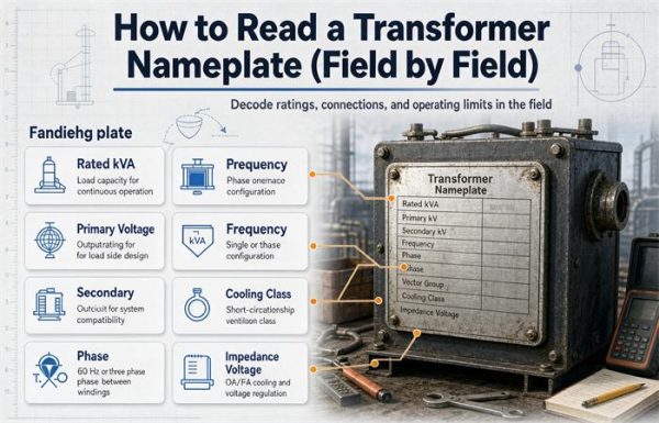
For the rest of the nameplate fields and how they interact, the nameplate reading guide covers the ones that get misread, and the IEC versus ANSI comparison explains why the same field can carry different meaning depending on which family the factory designs to.
Putting it together
FAQ
What is the difference between a core-type and a shell-type transformer?
In core form the winding wraps around a limb of the core, so the core sits inside the coil. In shell form the winding is a stack of flat pancakes and the core laminations press against both flat faces, so the core surrounds the coil. Everything else follows from that: cooling access, how short-circuit force is carried, how the unit comes apart for repair, and how compact it is for shipping. The electrical difference at the same rating is small, usually within a few tenths of a percent on full-load efficiency.
Which is better, core-type or shell-type?
Neither, and the honest answer is that for most buyers the question is not available. Core form covers roughly 250 kVA to 15,000 kVA at 138 kV and below, and in that range it is what factories build and stock. Shell form earns its place above that range, and in furnace, rectifier, traction, and mobile duty where short-circuit force and shipping envelope dominate. Below about 5 MVA you are often buying a wound core, which is a third construction that neither label describes.
At what rating does shell-type take over?
A Westinghouse engineering paper from November 1956 put the line at 15,000 kVA and 138 kV, with shell form preferred above it and core form preferred from 250 kVA through 15,000 kVA at 138 kV and below. That is engineering experience, not a standard clause, and no IEEE or IEC document states it. In practice the boundary has held because the manufacturing economics behind it have not changed.
Are shell-type transformers more efficient?
Not in any way you can bank. Shell form usually has lower no-load loss because the magnetizing path is shorter, and higher load loss because there is less copper in a sandwich winding. Take a representative 1,000 kVA pair with 1,500 W and 9,000 W for core form against 1,300 W and 9,900 W for shell form: the two break even at 47 percent average load. Above that load factor core form loses less energy, below it shell form does. The 30-year cost difference at 30 percent load is about $1,300 on a $30,000 unit.
Do core-type and shell-type transformers have different zero-sequence impedance?
Yes, and by a wide margin. A three-limb core with no delta forces zero-sequence flux out through the tank and frame, so Z0 can land anywhere from 0.75 to 2.0 times the positive-sequence value. Add a delta and it settles around 0.80 to 0.95 times. Five limbs, shell form, or a bank of three single-phase units gives the flux an iron path, so Z0 approaches Z1. On a 1,000 kVA, 480 V unit with 5.75 percent impedance, single-line-to-ground fault current ranges from 15,689 A to 22,019 A depending only on the core.
Why can’t I buy a shell-type distribution transformer in the US?
Because the factories that serve that market build core form, and below about 5 MVA many of them build wound cores rather than stacked ones. Shell form requires building the winding and the core around each other, which is economical for six large units a year and painful for four hundred small ones. The regional split has a history too: core form was General Electric’s line and shell form was Westinghouse’s, which is documented in the IEEE-hosted Engineering and Technology History Wiki archive of the Pittsfield works.
Does the core construction change the short-circuit rating?
It changes the margin, not the rating. Force on a winding goes with the square of current, so a fault at 20 times rated current produces 400 times the rated-load force. Shell form carries that force through core steel pressing on both faces of the winding, while core form carries it through external frames, bands, and tie rods. Both can be built to pass the same test. What differs is how much hardware it takes and how much margin is left at the end, which is why shell form is preferred where the fault level is high relative to the unit rating.
Free: Transformer Specification Checklist
The exact RFQ sheet our engineers use — send it and get a quoted proposal within 24h.
Download checklist