A transformer’s turns ratio is primary turns divided by secondary turns, and it equals primary volts divided by secondary volts. A 480 V to 208Y/120 V unit carries a nameplate ratio of 2.31 and a winding ratio of 4.00, and that gap is where most ordering mistakes start. What follows is the formula, six worked examples, and the 0.5% test limit that decides whether a unit ships.
This is not the article that explains why a changing flux induces a voltage. There are plenty of those, and one of them is a Department of Energy training handbook that ranks first for this term. This one is about a number you have to put on a purchase order, defend when a test sheet comes back 0.4% off, and live with for thirty years when two units share a bus.
The formula, and the direction that trips people up
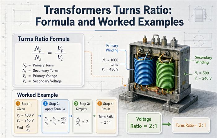
Everything below comes out of a single ratio. Set a as primary turns over secondary turns.
a   = Np / Ns            primary turns over secondary turns
a   = Vp / Vs            the same number, measured as voltage
Is  = Ip * a             current runs the other way
Vs  = Vp / a
Ns  = Np / a
Zp  = a^2 * Zs           impedance reflects as the square
That is the whole of it. The trouble is never the algebra. It is which side goes on top.
Two conventions, one reciprocal
The DOE handbook that owns the top of this search writes Vp / Vs = Np / Ns and then says the voltage ratio equals the turns ratio. So a 480 V to 120 V unit has a ratio of 4, and a step-down ratio is greater than 1. That is one convention, and it is the one American utilities and test crews use.
A large body of textbook and IEC-influenced material writes a = Ns / Np instead, so that a step-up transformer has a ratio above 1. Also defensible. Also a reciprocal of the first.
Both are correct. Neither is self-evident from the number alone, which is why a specification sheet that says “ratio 4:1” without naming the direction has told you nothing you can check. Four of the five top results for this term use one convention or the other and not one of them flags that the other exists.
The rule that ends the argument: write primary over secondary, and write the words next to the number. a = Np/Ns = 4.00, step-down cannot be misread. 4:1 can.
Two reasons to prefer primary over secondary rather than the reverse. A turns ratio test set reports high side over low side, and an IEEE nameplate lists high voltage first. If your arithmetic runs the same direction as the instrument and the plate, a 0.42% disagreement is a real finding. If it runs the other way, you will spend an afternoon on a unit that is fine.
A one line self check. You are holding a distribution transformer. The secondary voltage is lower than the primary. Your computed ratio came out at 0.25. You divided backwards. There is no case where a step-down distribution unit has a ratio below 1 in the primary-over-secondary convention, and no case where one has a ratio above 1 in the other.
Same ratio, different transformers
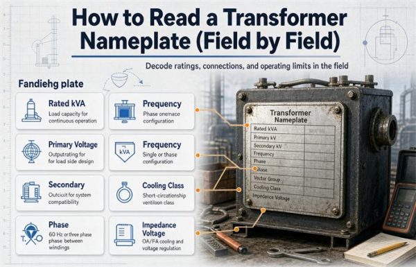
The ratio fixes volts. It says nothing about capacity. A 0.5 kVA control transformer and a 2,500 kVA substation unit can both be 4:1, and they differ by a factor of 5,000 in what they will carry. If you are still sorting out where the ratio and the kVA rating each live on the plate, the nameplate reading guide walks through both fields. Two documents are being written when a buyer asks for “a 4:1 transformer”: a voltage specification and a capacity specification, and only one of them is in the ratio.
Six worked examples
Example 1: 480 V delta to 208Y/120 V
This is the most common three-phase ratio in North American commercial work, and it is the one people get wrong.
The nameplate line voltage ratio is 480 divided by 208, which is 2.3077. A buyer reads that and writes 2.31:1 into a specification.
The winding ratio is a different number. The primary is delta, so each primary winding sees the full 480 V. The secondary is wye, so each secondary winding sees line voltage divided by the square root of three, and 208 divided by 1.7321 is 120.09 V. Winding ratio is 480 over 120.09, which is 3.997. Call it 4.00.
The two differ by a factor of 1.732, exactly. Neither is wrong. They describe different quantities, and only one of them corresponds to how many turns are on the core.
If you order against 2.31:1 and the factory builds to 2.31:1 of winding ratio, you receive a unit that delivers 480 V in and 480 divided by 2.31, or 208 V per winding, which on a wye secondary is 360 V line to line. That is not a subtle error. It is a rejected shipment.
Example 2: from a field reading back to a tap position
A technician puts a ratio set on a 480 to 240 V single-phase unit and reads a secondary of 234.1 V with no load.
Measured ratio: 480 divided by 234.1 is 2.050. Nameplate is 2.000. Deviation is plus 2.52%.
That number is not noise. It is almost exactly one 2.5% tap step. The unit is sitting on the +2.5% tap, which means more primary turns, which means fewer volts per turn, which means a lower secondary. Move the tap to nominal and the reading returns to 240 V.
Had the deviation come back at plus 0.3%, the answer would be different: inside the test tolerance, no action. Had it come back at minus 1.8% with no tap that explains it, you would be looking at a winding problem and calling the factory.
The point of the example is the direction of travel. A tap change moves the ratio, and the ratio moves the voltage, and the arrow points opposite to the way the tap label reads. Which is the next section.
Example 3: from volts per turn to a turn count
A small core is designed at 0.5 V per turn. The 480 V primary needs 960 turns. The 120 V secondary needs 240 turns. Ratio 4.00, arrived at from the core rather than from the voltages, and it lands on the same number.
That is not a coincidence, and it is the reason the ratio is a turns ratio at all. Both windings link the same flux, so both see the same volts per turn. Multiply by turns and you get the winding voltage. Divide one by the other and the volts per turn cancels, leaving turns over turns.
Example 4: a step-up unit ordered for a renewable project
A 0.480 kV to 34.5 kV collector transformer has a ratio of 0.0139 in primary-over-secondary form, or 1:71.9 the other way. Both are the same machine. The reason to write it as 1:71.9 is that nobody has ever built a winding with 0.0139 turns. When the ratio goes below 1, the colon form is easier to check against a winding schedule. For how these units get specified on the generation side, the step-up transformer guide covers the voltage pairs that actually get ordered.
Example 5: a single-phase unit with a centre tap
A 240/120 V secondary is one winding with a centre tap, not two windings. Ratio from 480 V to the full 240 V is 2.00. Ratio from 480 V to either half is 4.00. Both statements are true of the same unit because the tap divides the winding.
This matters when someone orders “a 4:1 transformer” meaning 480 to 120, and the supplier ships a 480 to 120 unit with a 60 V secondary, because 120 V was assumed to be the full winding. If you need a centre tap, say so, and say whether the 120 V is half of 240 or the whole secondary. Units of this shape are covered under single-phase cylindrical winding transformers.
Example 6: reverse feeding
Feed a 480 to 120 V unit backwards and the ratio inverts: 120 V in gives 480 V out, in theory. In practice the excitation current at 120 V on a winding designed for 120 V is normal, so the unit does work reversed, at a reduced kVA because the winding that was the secondary was not built to carry the primary current. The ratio is honest. The capacity is not. A transformer fed in reverse keeps its ratio and loses part of its rating, and the derating factor has to come from the factory rather than from arithmetic.
Turns per volt sits underneath the ratio
Both windings of a transformer share one flux, so they share one volts per turn figure. The core sets it:
E = 4.44 * f * N * Bm * A
volts per turn = 4.44 * f * Bm * A
At 60 Hz the leading constant is 266.4. A core of 0.0016 square metres running at 1.5 tesla gives 266.4 times 1.5 times 0.0016, or 0.64 V per turn. A 480 V winding on that core needs about 751 turns, and a 120 V winding needs about 188. Ratio 4.00 again.
Scale the core up and the turn count collapses. A core ten times the area carries ten times the volts per turn, so the same 480 V winding needs a tenth of the turns. This is why a 500 kVA unit has a few dozen turns on its low voltage winding and a 1 kVA control transformer has hundreds. The ratio stays wherever the design put it. The turn count, and everything that follows from it about how precisely a fault can be located, does not.
One consequence worth stating because it gets mixed up with the ratio. The ratio is set by turns. Saturation is set by volts per turn. They are separate limits, and a unit can hold its ratio exactly while running into saturation, because the flux density is what ran out, not the turns.
Three-phase: the square root of three lives in the connection
For a three-phase unit, the winding ratio and the nameplate line voltage ratio are related by the connection, not by the core.
| Primary | Secondary | Winding ratio a | Nameplate line ratio | Multiplier |
|---|---|---|---|---|
| Wye | Wye | a | line ratio | 1 |
| Delta | Delta | a | line ratio | 1 |
| Delta | Wye | a | line ratio divided by 1.732 | 1.732 |
| Wye | Delta | a | line ratio multiplied by 1.732 | 1.732 |
Read the 480 delta to 208 wye row of that table and it reproduces Example 1: 2.3077 times 1.732 is 3.997.
This table describes voltage magnitudes. It says nothing about phase displacement, which is the vector group, and a vector group mismatch is a separate failure mode that kills a paralleling attempt in a few cycles rather than degrading it over years.
The rounding problem in nominal voltage pairs
Standard nominal voltages are rounded. That is convenient on a drawing and it is a trap in a ratio calculation, because the rounding is not the same size in every pair.
| Pair | Implied ratio | Deviation from 1.7321 |
|---|---|---|
| 480 / 277 | 1.7329 | +0.046% |
| 208 / 120 | 1.7333 | +0.074% |
| 2,400 / 1,385 | 1.7329 | +0.046% |
| 600 / 347 | 1.7291 | -0.170% |
| 380 / 220 | 1.7273 | -0.276% |
The true relationship is 1.73205. A 600 V wye system has a line to neutral voltage of 346.41 V, which gets printed as 347. Divide 600 by 347 and you get 1.7291, which is 0.17% below the truth.
Now put that next to a test tolerance of plus or minus 0.5%. A technician who derives the expected winding ratio by dividing the two printed line voltages, then compares it with a measured value, has built a 0.17% error into the comparison before touching the unit. On a 380/220 system the phantom error is 0.28%, which is over half the tolerance band spent on arithmetic.
The fix is one line long. Convert to winding voltages first, using the actual square root of three, then divide. Never divide two rounded nominal numbers and call the result a winding ratio.
Under load, the ratio is not what the meter shows
The ratio predicts the no-load secondary voltage. Load it and the voltage falls, by an amount the impedance decides.
Take a 1,000 kVA unit at 480 V with 5.75% impedance and an X/R of 6. Resistance is 5.75 divided by the square root of 37, or 0.945%. Reactance is 5.67%. The approximate regulation is %R cos(theta) + %X sin(theta).
| Load power factor | Regulation | No-load 208 V becomes |
|---|---|---|
| 1.00 | 0.95% | 206.0 V |
| 0.85 | 3.79% | 200.1 V |
| 0.80 | 4.16% | 199.3 V |
So a 208 V unit reading 199 V at full load with a poor power factor is behaving exactly as designed. A technician who reports that as a ratio defect has compared a loaded reading against an unloaded promise.
Check the ratio at no load, or check it with a ratio set that energizes one winding and leaves the other open. A loaded voltage measurement is a regulation measurement, not a ratio measurement. Confusing the two is the second most common false alarm in this subject, behind only the reversed direction.
Taps change the ratio, and the sign is not universal
A tap adds or removes turns on one winding, usually the high voltage one. More primary turns means fewer volts per turn, which means a lower secondary. So a tap labelled plus makes the output go down.
On a 13.8 kV to 480 V unit with plus or minus 2.5% taps in two steps, and with 13,800 V actually applied:
| Tap | Tap voltage | Secondary at 13,800 V in |
|---|---|---|
| +5% | 14,490 V | 457.1 V |
| +2.5% | 14,145 V | 468.3 V |
| Nominal | 13,800 V | 480.0 V |
| -2.5% | 13,455 V | 492.3 V |
| -5% | 13,110 V | 505.2 V |
Two things fall out of that table. The range is wider than people expect: 48 V of swing on a 480 V nominal, which is 10%. And the direction is inverted from the label, which is why the first field adjustment on a new unit so often goes the wrong way.
There is a second trap. Not every manufacturer labels taps by the high voltage they correspond to. Some label by the resulting secondary voltage, so the plate reads 480, 468, 457 rather than plus 5, nominal, minus 5. The numbers look similar and mean opposite things. Read the plate legend, not the digits.
On a unit with an on-load tap changer the same arithmetic applies, with the added requirement that the changer be tested at every position rather than at nominal, because the pattern of deviation across positions is what diagnoses a contact problem. Those units are described under on-load voltage regulating transformers.
What plus or minus 0.5% actually lets through
Both major standards put the acceptance band at plus or minus 0.5% of the declared ratio. IEEE C57.12.90 covers liquid-immersed distribution, power and regulating transformers. IEC 60076-1 covers power transformers internationally and allows plus or minus 0.1% where the purchaser and manufacturer agree to it. The two are close enough to describe in one sentence and different enough that a specification should name which one it invokes, which is the distinction the IEEE versus IEC comparison sets out in more detail. The test procedure itself is one of the routine checks listed in the routine testing guide.
Now the part nobody writes down. A ratio test finds a deviation. How large a deviation a single shorted turn produces depends entirely on how many turns are in the winding.
| Turns in the winding | One turn is | Visible inside 0.5%? |
|---|---|---|
| 100 | 1.000% | Yes |
| 200 | 0.500% | At the limit |
| 240 | 0.417% | No |
| 500 | 0.200% | No |
| 960 | 0.104% | No |
| 2,000 | 0.050% | No |
| 5,000 | 0.020% | No |
At 240 turns, one shorted turn moves the ratio by 0.417%, which is inside the band. The unit passes. At 2,000 turns, you would need ten shorted turns to reach 0.5%.
This is the honest limit of the test, and it is worth saying out loud to a buyer who thinks a passing ratio test certifies the winding. It certifies the connection, the tap position, and gross faults. It does not certify that no single turn is shorted, because on any winding with more than 200 turns the arithmetic will not show it. Catching that requires excitation current, which responds to a shorted turn even when the ratio does not, or a sweep frequency response trace compared against a baseline.
Ratio mismatch in parallel costs more than it looks
Two transformers sharing a bus with slightly different ratios circulate current between themselves before any load is connected. The no-load voltage difference drives it through both impedances, and those impedances are deliberately small.
For two units of equal rating and equal relative impedance z, the circulating current as a fraction of rated current is:
Ic / Ir = p / (2 * z)where p is the fractional difference in no-load voltage. Put numbers on a 1,000 kVA, 480 V unit, which is 1,203 A:
| Ratio difference p | z = 5.75% | Circulating current |
|---|---|---|
| 0.5% | 4.35% | 52 A |
| 1.0% | 8.70% | 105 A |
| 2.0% | 17.4% | 209 A |
A 2% ratio mismatch burns 209 A of a 1,203 A unit, continuously, with nothing connected to the secondary. That current produces real losses, real heat, and no useful output. It also means the pair cannot be loaded to the sum of their nameplates, because the unit with the lower ratio carries the circulating current plus its share of the load and reaches its limit first.
Industry practice keeps the ratio difference within 0.5% for parallel operation, impedance within about 10%, capacity ratio within 3 to 1, and the vector group identical. Those four conditions are usually stated as a list. The ratio one is the only one that costs money while the plant is idle.
Autotransformers: same formula, one sixth of the iron
An autotransformer has one winding with a tap, not two separate windings. The ratio between high and low side is still the turns ratio, but the ratio that matters for sizing is the one across the series portion only.
For high side VH and low side VL, the series winding carries the difference and the whole load current, while the common winding carries only the difference in current. The result:
S_auto / S_winding = VH / (VH - VL)Take 480 V down to 400 V. The difference is 80 V, so the ratio of throughput to winding capacity is 480 divided by 80, or 6.0. A unit with 100 kVA of winding capacity passes 600 kVA of load. A two-winding isolation transformer doing the same job needs 600 kVA of winding. That factor of six is the entire commercial case for autotransformers, and it is also why the kVA on an autotransformer nameplate is not comparable with the kVA on an isolation unit’s plate.
The published buck-boost example makes the same point at small scale. A 1 kVA transformer rated 120 by 240 V to 12 by 24 V, connected as an autotransformer to boost 208 V to 230 V, becomes a 9.58 kVA unit for the purpose of sizing the overcurrent device. The nameplate still says 1 kVA, because the throughput depends on how it is connected and no plate can list every combination.
Two compliance points follow, both from NEC 450.4.
The overcurrent device must be rated at not more than 125% of the autotransformer’s rated full load input current, using the autotransformer throughput, not the two-winding nameplate. Where that lands between standard sizes and the input current is 9 A or more, the next standard rating up is permitted; below 9 A the allowance is 167%. And no overcurrent device may be installed in series with the shunt winding, the portion common to input and output, because opening it would leave the load energized from the primary through the series winding.
Second, NEC 450.4(B) requires that a transformer field-connected as an autotransformer be identified for use at elevated voltage. This is not paperwork. On an autotransformer the two sides are electrically continuous, so a 480 to 400 V unit on a system with one grounded primary corner can put 480 V to ground on a 400 V circuit. A buck-boost of a few tens of volts is benign. A 480 to 240 V auto connection is not, and the code treats the difference seriously.
One documentation note for anyone checking this against a supplier FAQ. NEC 450.4 is titled “Autotransformers 1,000 Volts, Nominal, or Less” in current editions. Several manufacturer documents still quote the older 600 V wording. The limit moved; the 125% and 167% arithmetic did not. A supplier quoting 600 V is quoting a superseded edition, which is a small thing to notice and a useful one.
For units built for this duty, the UL listed 480 V to 380 V transformer is an example of the export voltage pair where the autotransformer-versus-isolation decision gets made.
Reflected impedance and fault current
The ratio also decides what the downstream sees when a fault occurs, because impedance reflects as the square of it.
A 1,000 kVA unit at 480 V with 5.75% impedance has an ohmic impedance of 0.0575 * 480^2 / 1,000,000, or 0.01325 ohms. Bolted fault current is 480 divided by the square root of three times 0.01325, or 20.9 kA.
Scale the voltage up by a factor of 4 and the impedance on that side goes up by 16, which is why a per-unit study does not care about the ratio and an ohmic study cares about nothing else. If you are coordinating breakers in ohms, get the ratio right first. If you are working in per unit, the ratio has already cancelled out and the answer will be the same whether you wrote it as 4:1 or 1:4.
What to put in the RFQ
FAQ
What is the turns ratio formula for a transformer?
The turns ratio is primary turns divided by secondary turns, written a = Np/Ns. It equals primary voltage divided by secondary voltage, so a = Vp/Vs. Current runs the other way, Is = Ip times a. A 480 V to 120 V transformer has a ratio of 4.0. State the direction whenever you write the number, because the reciprocal convention is also in wide use and the two cannot be told apart from the digits alone.
Is the turns ratio Np/Ns or Ns/Np?
Both are in use and both are correct if the convention is stated. Primary over secondary gives a ratio above 1 for a step-down unit, which matches what a turns ratio test set reports and what an IEEE nameplate implies, since the plate lists high voltage first. Secondary over primary gives a ratio above 1 for a step-up unit, which some textbooks and IEC-influenced material prefer. Pick one, write it next to the number, and never issue a bare ratio.
What is the turns ratio of a 480V to 208Y/120V transformer?
Two answers, both right. The nameplate line voltage ratio is 480 divided by 208, or 2.31. The winding ratio is 480 divided by 120.09, or 4.00, because a wye secondary puts 208 divided by the square root of three across each winding. The two differ by exactly the square root of three, and only the winding ratio corresponds to the turn count on the core.
How do you find the turns ratio of a three-phase transformer?
Convert line voltages to winding voltages first, then divide. For a delta primary, the winding sees the line voltage. For a wye primary or secondary, the winding sees line voltage divided by 1.7321. A delta to wye unit has a winding ratio equal to the line ratio multiplied by 1.732. Dividing two line voltages directly gives the nameplate ratio, which is a different quantity and will not match a measured winding ratio.
How accurate does a turns ratio have to be?
Plus or minus 0.5% of the declared ratio under both IEEE C57.12.90 and IEC 60076-1, measured at every tap position. IEC permits plus or minus 0.1% where the contract says so. On a 480 to 120 V unit, 0.5% of a ratio of 4.00 is 0.02, so a measured ratio between 3.98 and 4.02 passes. Test instruments are usually specified ten times tighter than the limit so that measurement error does not consume the band.
Can a ratio test detect a single shorted turn?
Only on windings with fewer than about 200 turns. One shorted turn changes the ratio by 100 divided by the turn count, in percent, so a 240 turn winding moves by 0.417% and stays inside the 0.5% band, while a 2,000 turn winding moves by 0.05%. A passing ratio test confirms the connection, the tap position and gross faults. Finding a single shorted turn on a high voltage winding needs excitation current or a sweep frequency response comparison against a baseline.
Why does my 208V transformer read 200V when the ratio says 208V?
Because the ratio predicts the no-load voltage and you are measuring under load. A 1,000 kVA unit with 5.75% impedance and an X/R of 6 drops about 4.2% at full load and 0.8 power factor, which takes 208 V to 199 V. Measure at no load, or with a ratio set that leaves the secondary open, before concluding the winding is wrong. A loaded reading is a regulation measurement.
What to take away
The formula is short and nobody gets it wrong. What people get wrong is the direction, the square root of three, the sign on a tap, and the belief that a passing ratio test certifies a winding.
Four numbers are worth carrying into the next specification you write. A 480 delta to 208 wye unit is 2.31 on the plate and 4.00 on the core. A plus 5% tap takes 480 V down to 457 V, not up. The test band is plus or minus 0.5%, and a single shorted turn in a 240 turn winding fits inside it. And a 2% ratio mismatch between two paralleled units costs 209 A of circulating current on a 1,203 A bus before anything is switched on.
None of those are exotic. All of them are absent from the pages currently ranking for this term, which is why the arithmetic above is shown rather than asserted. Every number can be checked with a calculator and a nameplate.
Free: Transformer Specification Checklist
The exact RFQ sheet our engineers use — send it and get a quoted proposal within 24h.
Download checklist